


Colour Wiring Diagram
I recently posted an updated wiring diagram for the Norton Electra – taking the factory standard drawing, colorizing it and making the layout of the components simpler to follow on paper.
The drawing was a faithful reproduction of the original, and contained no alterations or aftermarket upgrades.
It can be found here
However, there is a strong desire to ‘upgrade’ this bike with a few components that make it easier to live with in the current day.
This article details two such upgrades – an update to the charging system, and swapping the ignition points for electronic ignition.
Charging System ‘Upgrade’
A very popular upgrade for the Norton Electra is to fit a single phase Lucas alternator stator, and aftermarket combined regulator/rectifier.
This is an “A REG ONE” unit from Al Osborn at AO Services.
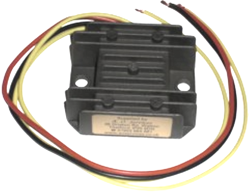
Al Osborne is the Norton Owners Club “Electrical Technical Advisor” – I am calling out Al over and above others in this article, as he is a Norton Lightweight Twin owner himself, and is a wealth of useful information and a big contributor to the community.
The installation instructions for fitting the “A REG ONE” can be found here

Electronic Ignition

A decent Norton Electra upgrade is to move from the old points-based ignition system over to Electronic Ignition.
A popular unit these days is the Pazon Sure-Fire

These are popular for two reasons:
- COST – the Pazon is one of the lowest price units available on the market at the moment, and they come with an amazing seven and a half year warranty!!!
- RELIABILITY – people are nervous of the ‘shake and bake’ units like the Tri-Spark, where everything is all in one single, miniaturised unit behind the points cover. The Pazon is a carbon copy of the Boyer Bransden unit with a stator plate (Pazon call it the Ignition Trigger) and a separate box of electronics (which Pazon call the Ignition Module)


In fact, the similarities with the Boyer Bransden units don’t end there – all the wires are the same color too!
Actually, Andy and Debbie from Pazon both used to work for Boyer Bransden!!!
Moving from points to a Pazon Sure-Fire electronic ignition is a pretty simple upgrade.
From a wiring perspective, the most important thing to note is that you will be moving from a pair of coils that are wired in parallel to series.
You should note that Pazon specify two 6 volt coils
Originally, the points make and break the positive (earth) side of each coil in turn.
The Pazon electronic ignition system uses a concept called “wasted spark” – with the two coils wired in series, they are energized together on every rotation of the camshaft.
You’ll note in the wiring diagram below that the condensers have been removed as part of the conversion to electronic ignition.
The color coding of the wiring is simple:
- The Red – this is the positive feed to the Pazon, and is usually picked up from the red wire that goes to the Coil positive terminal (a common ground is important).
- The Black – this is the negative supply FROM the Pazon TO the coils.
- The White – this is the negative feed to the Pazon. This joins in to the ignition switch (although some people will add a kill button).
- Black/Yellow and Black/White – these go from the Pazon Ignition Module down to the Ignition Trigger.

Wiring Diagram
Below is a simplified wiring diagram that incorporates the aftermarket regulator/rectifier and Pazon electronic ignition.
Two things to note:
- I have wired the reg/rec in so that the ammeter shows charge/discharge – many people will just wire the reg/rec directly to the positive and negative terminals of the battery.
That’s fine, but it means the ammeter won’t swing to show the affect of the alternator. - I have added a separate fuse on the reg/rec output – this is, at least in my eyes, best practice.
If there is an issue with the alternator stator or the reg/rec you have fuse protection, yet still stand a decent chance of getting home.
Again, others will choose not to do this.
Here is the wiring diagram.
Norton Electra 400cc twin from Feb 1963 wiring diagram with aftermarket regulator/rectifier and electronic ignition PNG 3066 x 1841
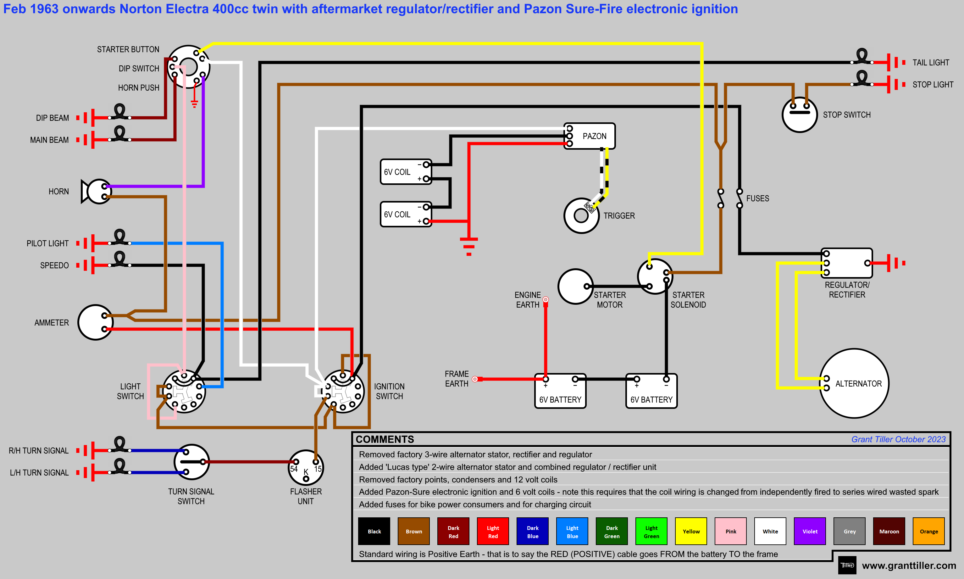
This is available as a PDF too – it can be downloaded here.
Wipac ‘vs’ Norton
Norton made a minor change between the schematic that Wipac created originally and published, and the version that Norton later published in their factory workshop manual.
The change is pertaining to the behaviour of the lighting – in the “emergency” ignition switch position, the lighting is not operable based on the original Wipac schematic.
However, with the Norton’s later revision, the lighting behaves the same in both normal “ignition” and “emergency” switch positions.
I assume this change was due to the need or desire to get home safely under the cover of darkness with lights on!

Norton Electra 400cc twin from Feb 1963 (updated) wiring diagram PNG 3066 x 1841
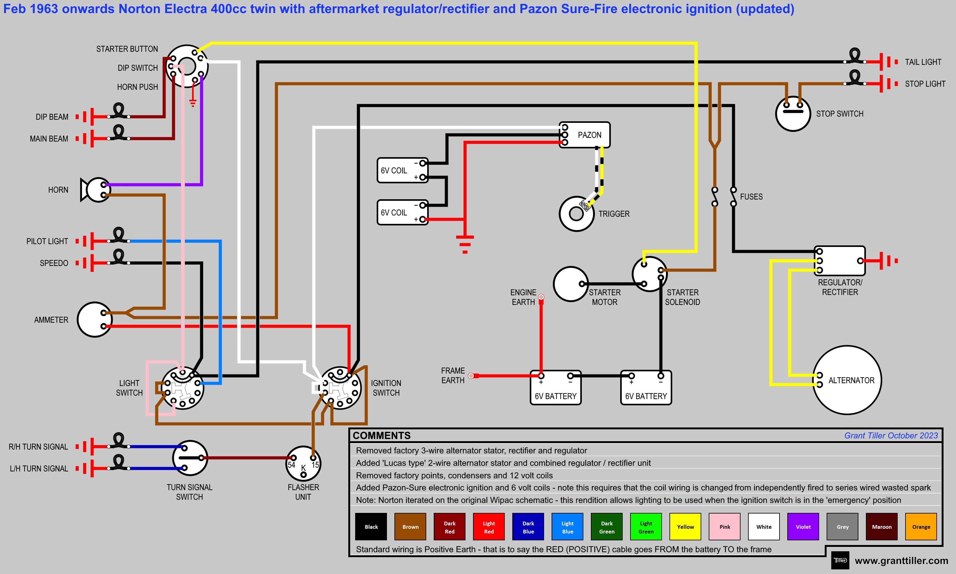
This is available as a PDF too – it can be downloaded here.