


This is a custom wiring diagram for David Stovin on the Commando and British Motorcycle Mechanics Facebook Groups
Electronic Ignition
David has fitted a Boyer Bransden MK3 electronic ignition to his bike.
A really popular Norton Commando upgrade is to move from the old points-based ignition system over to Electronic Ignition.
One of the most common units of the time is Boyer Bransden, who have been around since 1969.

They are still going today, and their website can be found here.
Moving from points to Boyer electronic ignition is a pretty simple upgrade.
From a wiring perspective, the most important thing to note is that you will be moving from a pair of coils that are wired in parallel to series.
Originally, the points make and break the positive (earth) side of each coil in turn.
The Boyer electronic ignition system uses a concept called “wasted spark” – with the two coils wired in series, they are energized together on every rotation of the camshaft.
You’ll note in the wiring diagrams below that the Ballast Resistor and Condensers have been removed as part of the conversion to Electronic Ignition.
The color coding of the wiring is simple:
- The Red – this is the positive feed to the Boyer, and is usually picked up from the red wire that goes to the Coil positive terminal.
- The Black – this is the negative supply FROM the Boyer TO the coils.
- The White – this is the negative feed to the Boyer. This joins in to the White/Blue wire that used to feed the Ballast Resistor that you are removing. As standard, this goes up to the big connector block under the tank, where it’s joined to the White/Yellow that is the kill switch on your left side handlebar switch cluster.
- Black/Yellow and Black/White – these go from the Boyer black box (they call it the Transistor Box) down to the Stator Plate that sits behind the points cover.
Regulator/Rectifier
David has also fitted a Boyer Bransden Power Box regulator/rectifier.

Wiring Diagram
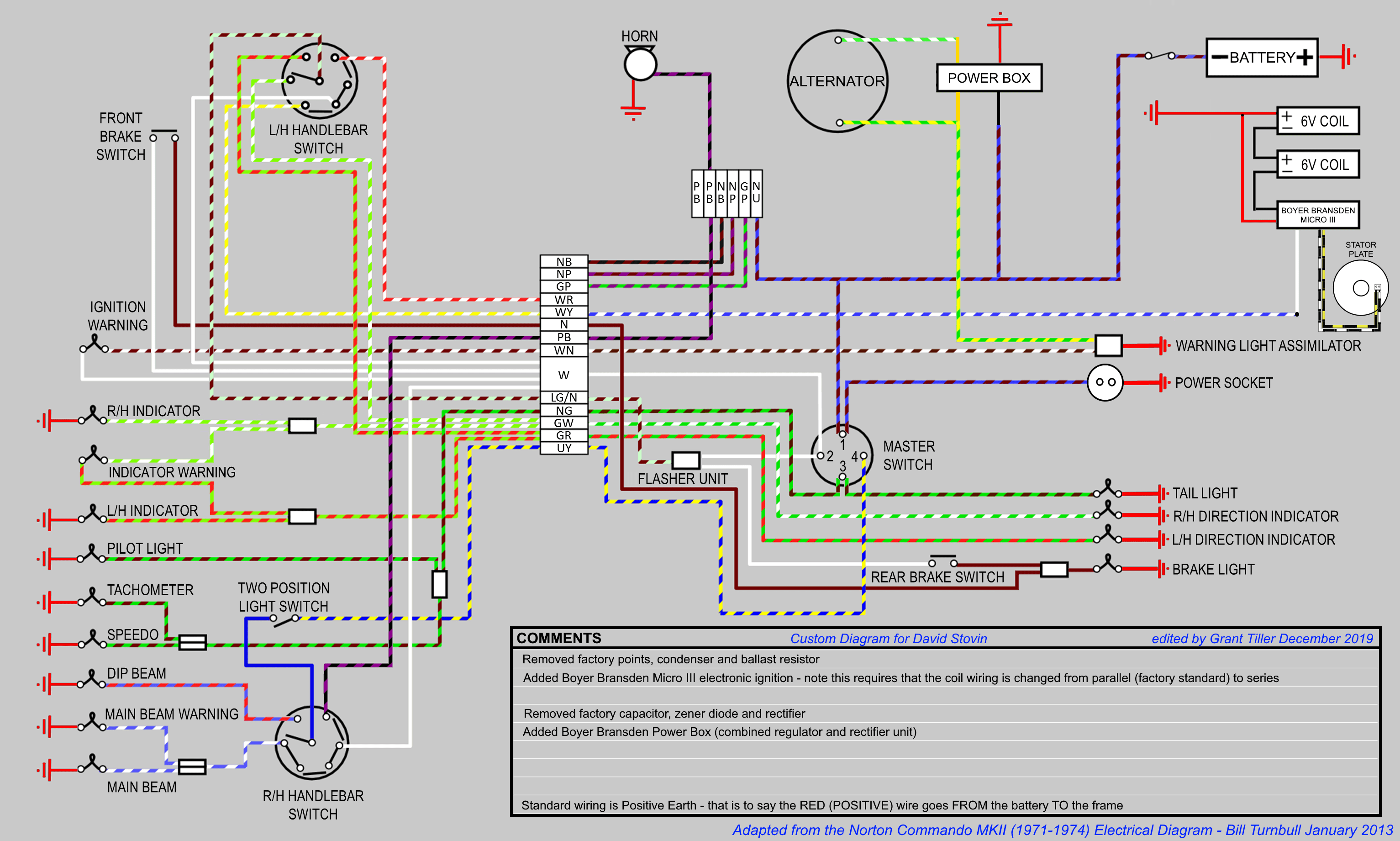
Here is the diagram:
Custom Norton Commando Wiring Diagram – David Stovin PNG 3066×1841
Warning Light Assimilators
It is important to note that MOST aftermarket reg/rec manufacturers do not support either the pre-MK3 Lucas 3AW silver can warning light assimilator OR the MK3 one.
Boyer Bransden are very explicit in their instructions for the Power Bow – they have even made an alternative Power Box model that includes a charge warning light.
Other manufacturers (PODtronics, SPARX and the Tri-Spark MOSFET units) either mention it in their smallprint/FAQs or neglect to mention it at all.
As such, I would recommend NOT using the original assimilator and consider your alternatives.
You could replace your assimilator with a solid state equivalent like the CoolCat Express (warning: you have to buy positive SS3AW-P or negative SS3AW earth)
Alternatively, you could follow my recommendation and buy a Charge Warning Light instead.
A warning light assimilator tells you that the alternator stator is producing an AC output, whereas a Charge Warning Light tells you that the battery is charging, the reg/rec is working and it gives you much more useful information about performance of the charging system and the state of charge.
I personally recommend the Improving Classic Motorcycles “Standard” Charge Warning Light. This model wires in to the standard incandescent lamp, so it looks better than a modern LED. It matches all your other warning lamps, which is particularly important on the MK3 with it’s instrument ‘console’
The ‘brainbox’ is about the size of a postage stamp, and can easily live inside the headlight bucket or under the MK3 ‘console’