


I often help people with their motorcycle wiring issues – both in ‘real life’ as well as on the Facebook groups and various forums.
I’m pretty good at wiring, and fault finding so am not scared to roll my sleeves up and get stuck in.
They say a picture paints a thousand words, so I often refer to pics when I’m trying to help someone.
Elsewhere on this site, you’ll see various schematics based on the originals that have been modified to accommodate common upgrades – in particular electronic ignition and modern regulator/rectifier units.
Thanks to Les (L.A.B) from the Access Norton forum who helped immensely with the initial work on this, and keeping me honest.
1968 Norton Commando Wiring Schematic
These are the pre-1971 bikes and have the ammeter in the headlight shell, as well as the Wipac Triconsul type handlebar switch.
The wiring is very simple, and more like the Atlas than what came to be familiar with the Commando.
Note that I have included the Front Brake Switch as standard – this was a US requirement, that didn’t appear on the earliest UK bikes.
1968 Norton Commando Wiring Schematic PNG 5600×3960

This diagram is also downloadable as a PDF from HERE

1971 Norton Commando Wiring Schematic
This is often referred to as the “Interim” model.
It is distinguishable by the three pin master switch (ignition key switch) which was Lucas part number LU39565.
These were made ONLY for the Norton Commando, and are no available as an aftermarket replacement.
If you are not comfortable rebuilding the switch, most people choose to go for the LU30552, which IS readily available.
You can find an article on ignition switches here, that may be of interest.
1971 Norton Commando Wiring Schematic PNG 5600×3960

This diagram is also downloadable as a PDF from HERE
1972 onwards Norton Commando Wiring Schematic
The 1972 onwards schematic covers 750 and 850 bikes and has the much more familiar four pin master switch (ignition key switch)

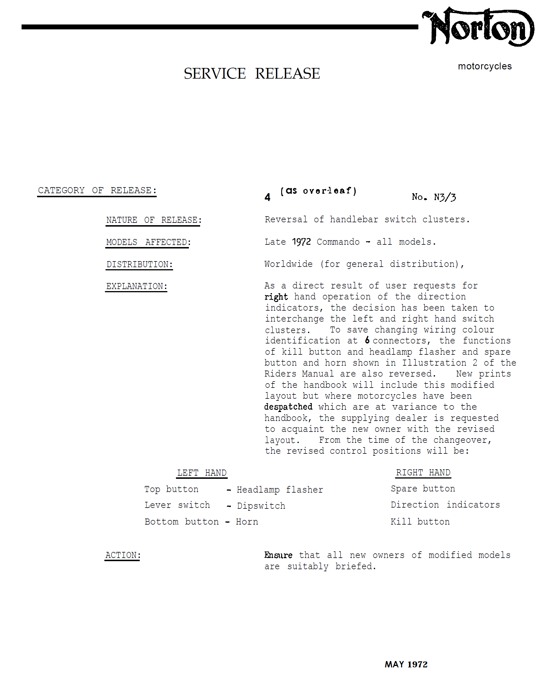
One modification to be mindful of – in fact one that was wholly supported by Norton back in the day is the swap of left and right handlebar switches.
It makes sense to most to have the turn signal switch on the left side, so you can keep your hand on the throttle/brake.
However, at the time, not everyone liked this and in support, Norton sent out a Service Bulletin to the distributors and dealers instructing them to swap sides according to the customer’s wishes.
Based on discussion with the community, I have drawn my schematics, labelling the handlebar switch with Turn Signals as “L/H HANDLEBAR SWITCH” (as per the original factory workshop manual) but do bear in mind, they could be swapped on your bike.
L/H turn signals is in line with the MK3, and what later became “standard” across all motorcycles.
1972 onwards Norton Commando Wiring Schematic PNG 5600×3960

This diagram is also downloadable as a PDF from HERE
MK3 Commando
During the manufacture of the MK3, Norton and Triumph were coming together, and they were often feeding from the same parts bins.
We have noted some anomalies between the handlebar switches while the MK3 was in production, as they frequently used the Triumph T140E switches, which look the same, but have a couple of small wiring differences.
Left handlebar switch the U (blue) used by Norton (and illustrated in the factory workshop manual) has been replaced with a UY (blue/yellow) cable. This connects to the U (blue) of the right handlebar switch inside the headlamp bucket.
Right handlebar switch there is no S (slate grey) instead, the single “hot” negative from the pin 2 of the Master Switch (ignition key switch) is jumpered for both engine run/kill switch and the starter button.


Another element of the MK3 that sometimes causes confusion is the wiring around the Warning lights.
The factory workshop manual shows the following:
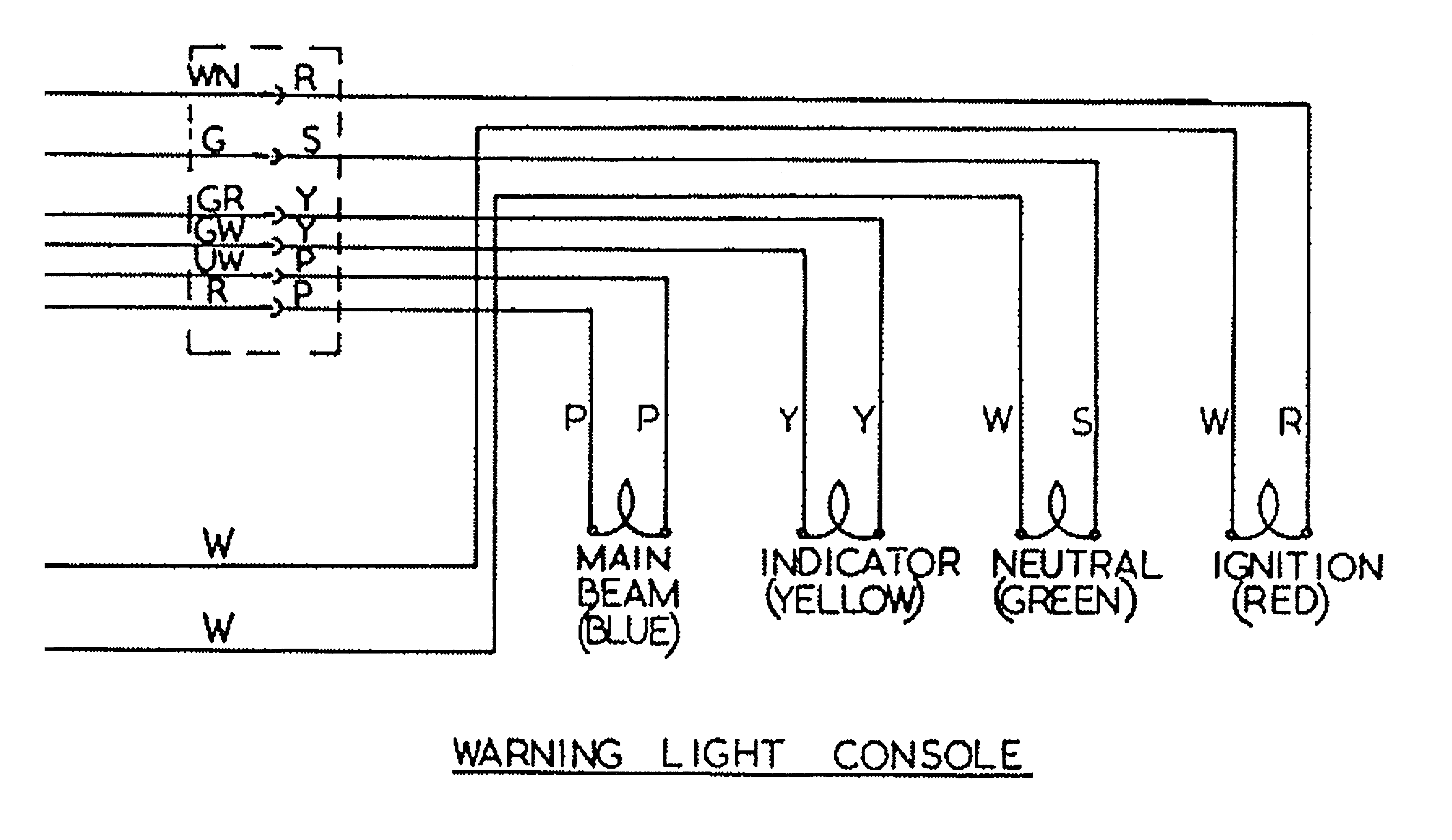
I have covered this in more detail in a separate article, which can be found here.
But in short, the cable colors used for the sub-console wiring harness were not the same all the way through MK3 production – so certainly something to watch out for!
1974 Norton MK3 Commando (Early) Wiring Schematic
1974 MK3 Early Bikes – there were around 2,000 bikes that were built around the December 1974 timeframe that have three additional fuses that can be found in the headlamp bucket.
These bikes are also wired with the old Lucas 3AW 3 wire ‘silver can’ assimilator.
1974 Norton MK3 Commando (Early) Wiring Schematic PNG 5600×3960

This diagram is also downloadable as a PDF from HERE
1975 Norton MK3 Commando Wiring Schematic
This is the most common configuration, and takes us through to the final Commando that rolls off the production line.
1975 MK3 (Original)
1975 Norton MK3 Commando Wiring Schematic PNG 5600×3960

This diagram is also downloadable as a PDF from HERE
1975 Norton MK3 Commando (Canadian Market) Wiring Schematic
For the Canadian Market, there were legal requirements around the headlamp being on while the engine was running.
The wiring diagram includes changes needed (swapping out the Warning Light Assimilator 06-6393 for the Headlamp Warning Unit 06-6392).
Note that a different Master Switch (ignition key switch) is also required – the key switch differences for Canada are covered here in a separate article.
This is covered in the Factory Wiring Diagram, by notes.
While the Headlamp Warning Unit is available from our friends at Andover Norton, the Canadian key switch LU30825 is not available, and must be rebuilt manually.
1975 Norton MK3 Commando (Canadian Market) Wiring Schematic PNG 5600×3960

This diagram is also downloadable as a PDF from HERE
NOTE:
A couple of points about the way these diagrams have been drawn:
- The diagrams on my site are schematics – the components are not drawn in the physical location on the bike. Instead they are drawn in locations that make the diagram the easiest and most logical to follow.
- Where the same colour wire goes in to and out of a single connector, that connector has usually been omitted from the drawing.
It’s obvious on the bike, is easy to spot and easy to troubleshoot.
Leaving them off the diagrams makes them a LOT easier to read, and considerably less cluttered. - Wherever the earth or ground side of a component goes back to the battery, the drawing shows a red earth symbol:

In reality, this could be connected either to a red wire in the bike’s wiring harness (loom) OR it could be attached to the frame or engine of the bike.
I have shown the red earth symbol each time in order to massively simplify the diagram, and make it a lot easier to understand for everyone.
I have also coloured them red as a gentle reminder that these bikes are wired positive earth!
Hopefully these will help someone – don’t be scared of electrics.
The trick is to not be overwhelmed, print out the diagram, and follow each line.
There is no hurry, take your time.
And if you get stuck, reach out – there are lot’s of people willing to help!
This article is from a pair that covers the Wiring Diagrams for the Norton Commando:
- Norton Commando Wiring Diagrams – colorised and corrected
- Norton Commando Wiring Diagrams – individual circuits
As always don’t hesitate to reach out if you need any help or advice.
Grant,
I’m working on a 650SS that has been converted to Boyer and Tympanium voltage regulator. The wiring is a mess and the 650SS didn’t even have a fuse or master switch. Your Pre-1971 drawing is close to how I’m going to wire it. It needs three changes other than the EI and VR. There is no front brake switch. The white wire that connects to the ammeter I’m going to connect the the switched side of the master switch. also, the white/brown wire that connects in the drawing from the un-switch side of the master switch to the headlight switch I’, also going to connect to the switched side. So, the master switch will turn the bike off completely.
If you’re looking for something to do, it would be helpful to have a diagram to help me remember as I wire. Don’t give it a second thought it you don’t have the time.
Greg…
Hi Greg,
Absolutely! I’ll take a look, and get something posted!
Hi Greg,
Here you go:
Click Here
Don’t hesitate to let me know if you require any tweaks or edits.
Cheers!
Hi Grant
I have a 1971 Commando and am trying to trace the wiring and am finding that my loom does not fit either of the wiring diagrams shown.
It seems to fit exactly as the 1971 three wire switch but mine is fitted with an ammeter so my question is, has the wiring been modified by a previous owner and how should the ammeter be connected into the circuit.
Also when I use my indicators the ammeter shows an intermittent discharge is this correct.
Hoping you may have time to give me an answer
John
Hi John,
The earlier bikes with standard ammeter wiring are very very different – much simpler and with only a two position ignition switch (on or off).
It sounds to me like a previous owner has indeed run the wires for an ammeter.
I did a custom wiring diagram for Vaughan, a guy on facebook who has got exactly the same setup as this.
The only difference is that his bike is a 1972 model, so has the four pin master switch.
Have a look here: https://granttiller.com/custom-norton-1972-commando-wiring-diagram-vaughan-rochford
It maybe closer to your machine than the factory diagram!
Thank you Grant. I truly appreciate your working on this project.
Happy to help Conrad!
It’s great to hear these are being used by people!
Hello Grant – I’ve a 1971 Commando & I found the wiring diagram you provided above very useful. Although my bike is a 71 – it was delivered in early January 1971, so was presumably built towards the end 1970 – although I understand from the Vintage Motorcycle Club, that the records show it was built to a 1971 spec. Despite this, the headlight is the “halo” type and has an ammeter and only 1 warning light. The wiring loom has an assimilator and a Fiamm horn & relay. Obviously not things on the wiring diagram. I’ve bought a new loom but connecting it up has not been as straightforward as I’d imagined!🤣
I wasn’t sure if the relay was needed (the wires to the switches look to be the same thickness as the rest of the loom) despite this I tried to incorporate it but it doesn’t seem to have worked out & I’ve had difficulty finding an exact wiring diagram for the Fiamm relay. It has the usual #87 terminal (going to the horn) & the #86 is connected to the 30/51 terminal – there is another “bladed” terminal (unmarked) & a wire coming off relay (again unmarked). Have you any advice about the need for relay & assimilator & how they should be wired in?
Thanks in advance – cheers
Davy
The ammeter, red warning light and switch were in the 1968-1970 7 inch headlight.
Confusingly the red light was for the high beam warning light!
There was no assimilator on these bikes.
The ammeter was dropped the following year, and three warning lights were in the headlamp shell until the MK3 850 came along.
The fiamm horn and relay were a popular upgrade of the time – although not standard.
The only relays used on the Commandos as standard were on the Interpols (police bikes)
The relay pinout is pretty standard – but don’t forget on this bike you are making and breaking the earth on the handlebar switch.
I’ll make a diagram for you – do you have any other upgrades on your bike that need to be included (electronic ignition, regulator/rectifier etc) or is is standard?
Are you using the original tricon switch or have you fitted an aftermarket one and lost the use of the flasher button?
Hello from New Zealand Grant,
Many thanks for making these awesome wiring diagrams available!
Have just rewired my Canadian version Mk3, after upgrading to 3 phase alternator, Trispark ign and Podtronics unit. Bought a full set of new wiring looms, unwrapped each one, removed all the redundant wires then re-wrapped.
Just doing the headlight loom now, however all the connections are bullet connectors, whereas the original had small white plugs inside the headlight shell. I contacted the manufacturer in UK, who advised that the small plugs were causing problems for many owners, so they replaced them with bullets of which there many. I am thinking of cutting of the bullet connectors and plugs from the handle bar switches and using waterproof Deutsch style connectors. Just wondering if you have any further suggestions?
Kind regards
Richard
Glad you like the site – hopefully it’s been useful during your project!
Yes, I have heard that Autosparks (the makers of the Lucas/Wassell and the Andover Norton harnesses) have stopped supplying the correct plugs.
This is a decent source for connectors:
2 pin: https://www.tricor-andy.com/product/2-pin-connector/
4 pin: https://www.tricor-andy.com/product/4-pin-connector/
6 pin: https://www.tricor-andy.com/product/6-pin-connector/
Tricor Andy Gregory is the guy that makes the Sparx aftermarket handlebar switches.
I have also had some great luck with these guys.
They sell replacement pins that allow you to put new cables in the original connectors:
https://www.bikerstoolbox.co.uk/acatalog/Multi-Block-Connectors-p1.html
There’s no problem with chopping off the plugs and using standard bullet connectors instead.
But I would recommend that you use a decent crimp tool and insertion tool if this is the route you plan to take.
A good source for wiring bits on your side of the pond is British Wiring.
They are based in Berks County, Pennsylvania but that’s a lot nearer to Canada, so shipping costs will be lower.
http://www.britishwiring.com
The company was originally setup by Roger Davis, who owns Autosparks (the manufacturer of the harness)
And although he sold the US company a few years ago, they are still Autosparks stockists and keep an excellent stock of parts.
I use (and recommend) Deutsch connectors – they are the best quality by far versus the other multi-way connectors available.
The slightly smaller DTM connectors can take enough current and versus something like the superseal connectors, they are a lot smaller and easier to hide away.
The other thing I like about them is that you can disassemble the plugs and sockets which is handy if you need to pull wires through holes and grommets.
Hope that helps!
Hi Grant,
My apologies for the late reply, just found your reply on access norton forum without any notification
Anyway, many thanks for your reply and useful information. Have decided to use the Deutsch DT plugs, as they have 2 sizes of #16 terminals whereas the DTM plugs have only 1 size and are only rated at 7.5 amps. Having a few problems with my Sparkbright led charging indicator light. At a steady speed, it sometimes flashes red for a few seconds before going back to green again?
Kind regards from New Zealand
Richard
I usually prefer the https://www.improvingclassicmotorcycles.com charge warning lights, as you can use the existing lamp so that everything still matches (particularly useful with the MK3)
However, I have a couple of the Sparkbright LEDs – I have one in the toolbox, and use it as a quick test tool for battery condition (saves breaking out the multimeter)
The other I have fitted on a cafe racer.
I am amazed by how much difference in behaviour I see depending on how close to the battery the unit is wired.
If it’s directly on the battery it seems far more stable than if it is at the front of the bike via several connectors and the ignition switch.
I also notice a difference on bike wired with the blue can capacitor versus bike that have it removed – so it seems that the smoothing must make a difference to the reaction speed of the status monitor – ironing out the bumps to take away anything that may throw a sporadic status change.
It’s no big deal, just an observation.
Hi Grant
I have a oct 71 commando bought in 72, i was thinking about adding indicators but looking at the wiring diagram im a little confused about how the warning light works and gets its earth, it looks like it is connected between the left and right live feeds to indicators, surely that will connect all four indicators at once and still does not explain the earth.
The rest of the wiring all seems pretty obvious, im assuming the fasher unit is a two pin unit and does it have to be of a certain value.
Many thanks
Bern
Hi Bernie – great to hear from you!
Yes, you are right, the indicator warning lamp looks weird in how it is wired – but that’s the way it was done back in the day.
– if you turn on the left turn signal, the earth for the warning lamp is achieved via the right front and right rear turn signal lamps.
– if you turn on the right turn signal, the earth for the warning lamp is achieved via the left front and left rear turn signal lamps.
Because the wattage of the warning lamp is so low (¼ watt) compared to the two turn signals that it’s pulling the earth through (21 watt each) it is enough to make the warning lamp glow brightly, but the turn signals not glow at all.
It is important on our old bikes to run the correct wattage bulbs, otherwise you may experience the turn signals flashing at different speeds, or all four turn signals flashing independent of whether you are signalling left or right.
These flasher units are still available from the usual suspects, including our friends at Andover Norton:
https://andover-norton.co.uk/en/shop-details/17959/flasher-unit-12v-35048a-06-2045-
However, if you are considering LEDs or anything different from the usual, you may want to think about using a more modern flasher unit instead.
Something like this works well, as they have a positive earth version available:
https://www.classiccarleds.co.uk/collections/indicator-relays-electronic/products/12v-electronic-indicator-flasher-relay-classic-car-with-oe-click-x-l-p-2-3-pin?variant=8299346853983
These will also allow you to fit incandescent lamps now, and swap to LEDs in the future if you decide to.
One thing worth remembering with the Lucas turn signals – these get their positive feed from the ‘stalk’ of the indicator.
These are made of chromed plastic, so the quality of the connection here is the first suspect if you have any issues at all with your turn signals!
Reach out if you have any further questions, and I’ll do whatever I can to help!
Grant.
Hi Grant,
Thanks for posting these diagrams. I’ve been trying to sort the rats nest of wires under the tank from a previous owners attempt at fitting a Boyer ignition. The old black and white diagram I had was not much help!
The colour coding for the coils, not even marked on my diagram, helped make sense of it all.
Interesting that I seem to have a Mk3 loom fitted to my Mk2a, it has the WR and WP wires for the starter solenoid but obviously nothing for them to connect to. It may have been fitted by a previous owner but as the bike is original and low mileage I’m wondering if the later Mk2a’s had these looms from the factory?
Thanks again for saving me much time and head scratching.
Mark
Hey Mark – great to hear my efforts are helping someone!
I have certainly not seen a MK3 harness on a MK2a to date.
In fact, if anything it kinda works the other way – in the first couple of thousand MK3s they used a weird harness which was an evolution of the old one (it even retained the old 3AW silver can assimilator)
One major difference was that it had an additional three fuses inline which were all hidden away in the headlight bucket – this is often a source of confusion!
Grant
Hi I have a 1970 Commando but the kill button doesn’t work but looking at the diagrams can’t see how to get going can you help thanks Dave
Hi Dave,
The 1970 was the first year that Norton moved away from the Wipac Triconsul switch, and across to the aluminium Lucas units that were integrated into the lever perches.
Do you have electronic ignition?
Is it fed from the WY (white/yellow) wire that comes from the handlebar switch.
This wire goes ‘hot’ when you turn on the ignition switch, and should go dead when you press the button.
Out of the four push switches on the handlebars, this one is unique compared to the other three, as it is the only one that is push-to-break.
The other three are push to make.
So this would be the first area to check!
If the ignition is wired in correctly to this White/Yellow and it is permanently life, even when the button is pressed, it could well be the case that the switch needs rebuilding.
It is a little fiddly, but take your time – after fifty years, the contacts become corroded.
I clean them with a fibreglass pencil and some wire wool, and they are usually good to go again!
Hi Grant,
Thanks for making wiring information available.
I’ve been rehabbing a 1973 Norton Commando 850 with my Uncle. I’m curious if I can add some notes and clear up some confusion when I was wiring the bike. It would have helped during this project.
-Kiel
Help yourself to any of the content on the site.
If you have any other questions, feel free to drop me a note and I will help you out as best as I can.
Grant,
I’m working on a MK3 Canadian and having issues with the starter. Installed a new solenoid and when I press the starter bottom I get 1.57v on terminal red/white connected to S terminal on the solenoid. No noise when bottom is press in. I bypassed the solenoid and the starter spins. When I removed the solenoid, I checked for continuity and I do get a beep from the S terminal to ground. From I terminal to ground no continuity. When checking S to I terminal I get nothing. I got this new solenoid from Andover Norton and they are saying I should have 12V on the red/white wire going to the S connection on the solenoid before I press the starter switch. I this correct? I’ve been looking at your great diagram and still scratching my head.
Hi Gary,
There are two smaller terminals on the original starter solenoid.
One is marked “S” which is for switch – it is the WR (white/red) from the handlebar switch.
The second terminal is marked “I” which is ignition – it is the WP (white/purple) that goes to the ballast resistor between the coils.
If you are using electronic ignition, there is not need to connect the WP, as the ballast resistor and condensers are removed.
It is essential that you have a decent positive feed to the metal mounting bracket on the solenoid – without this, the switch won’t operate at all.
There should be the full voltage of the battery at the “S” terminal when you press the starter button.
There should be zero voltage at this terminal at all other times.
On your well appointed MKIII starter rotation diagram you show the starter spinning Clockwise. I have read reliable accounts by world class Norton mechanics that claim the starter spins the other way. Upon bench testing, my starter spins counterclockwise. I saw a video of these very skilled Canadian Norton builders put juice to a rebuilt starter, and it spun counterclockwise. What is the 411.I am baffled.
Hi Chris, and thanks for reaching out!
I have stripped our own MK3 a few times (including converting it to four brush/four coil using the Harley unit for donor parts).
I can confirm unequivocally that the starter motor rotates clockwise.
…and in honesty, I am not sure what other detail I can add to my article to prove it (note also in the excerpt from the Norton Factory Worksop Manual at the bottom of the article in the very last pic, it references in the top right “PRESTOLITE STARTER MOTOR (CLOCKWISE ROTATION ON DRIVING HEAD)
My content is often disputed by “world class Norton mechanics” and I frequently get hate mail from “experts” telling me I’m wrong, I am an idiot, and ‘nothing more than an enthusiastic hobbyist’
That’s fine by me, as I know my advice is correct, and it’s up to the reader if they take it or leave it.
Grant on your 75 mark 3 diagram you completely omit the wiring for the ignition control box . you only show assimilator warning . Do you have the wiring diagram for that box. the new harness colors don’t match what took off. any help is appreciated thanks mark
Mark – I have not omitted the “Ignition Control Box” from the MK3 diagram.
In the case of the 1974 MK3 (early – three additional fuses in the headlamp shell) you can see the Lucas 3AW 3 wire ‘silver can’ assimilator – this was used for the first 2,000 bikes off the production line.
For the 1975 MK3 (Original) the “Ignition Control Box” is labelled Warning Light Assimilator to reflect what it actually is.
For the 1975 MK3 (Canadian Market) it is labelled as Headlamp Warning Unit to reflect the fact the unit is responsible for routing power to the headlamp when the bike is running.
There are no omissions in my diagrams.
Hope this helps.
On the original factory harness, Norton ran the cables for the Rest of World and Canadian spec bikes alongside each other.
The only difference was the module and the ignition key switch.
While the Canadian Headlamp Warning Unit is still available https://andover-norton.co.uk/en/shop-details-2/16803/w-light-control-unit-canada-
The special Canadian ignition key switch LU30825 is not available at all.
I did a seperate article on how the Canadian key switch is different internally https://granttiller.com/how-to-spot-a-canadian-ignition-key-switch
For the aftermarket wiring harness (both sold by Andover Norton, as well as the ones sold under license by Wassell/Lucas) have the cables for the Rest of World spec only – they have dropped the extra wires for the Canadian Headlamp Warning Unit.
Grazie mille (Thanks a lot from Italy)!
I tried to modify an existing wiring loom but at the end I decided to start from scratch. Andover sells cables (also to those living outside England), here you can find the bigger 5 pin connectors (https://www.britishwiring.com/5-Way-3mm-Pin-Socket-Connector-p/c825.htm), the smaller one, as you mentioned, can be found here (https://tricor-andy.com/product/2-pin-connector/). I also asked Andover if they sell modified looms for Trispark regulator and ignition, but they don’t.
Thanks so much for your message Ivo!
Tricor Andy sells the three types of plugs (2, 4 and 6 pin) used on the MK3 handlebar switch gears.
He makes and sells the Sparx aftermarket switches, and uses them on these.
Covering left and right side:
2 pin Connector
4 pin Connector
6 pin Connector
Useful for UK and Europe – but your link maybe better for our US friends, so thank you!
Two good resources over this side of the pond for cable etc are:
AES (Auto Electric Supplies)
Vehicle Wiring Products
I use both companies, and they are brilliant!
Hello Grant,
What a wonderful treasure chest of info you have on this site!
I am about to start wiring a 71 Commando from scratch. I almost understand the diagrams, except for the wire connections shown around the horn. My understanding is that there should be one PB connection to the horn, so why do you show a second PB box with no wire, NB, NP & GP going nowhere and an unconnected NU box? Also, what purpose does the WR on the LH switch have – it doesn’t seem to go anywhere?
Thanks for any clarification.
Graeme
Thanks for your kind words Graeme!
Not sure who made the decision, but Norton Commandos were all supplied with some of the Interpol (police bike) wiring included in the harness.
…I dread to think how much money they would have saved if the didn’t include this!
That additional PB (purple/black) cable that goes nowhere is for the police horn, which had hi/lo hooters.
Aftermarket harnesses (by the likes of Andover, as well as the Wassell/Lucas ones have dropped the police cabling, as it’s superfluous for most of us)
NB, NP and GP were also for sires and flashing lights too.
The NU (unswitched negative feed) was there to power it all.
The WR (white/red) on the handlebar switch was there for an electric starter.
It was always on the cards that the Commando would be fitted with one, even though we didn’t actually see it on a bike until the 1975 MK3.
Hope this helps,
Grant
Grant,
You have a wiring diagram labelled as Early 1974 Mk3, but I think it should be Early 1975. I have a 1975 Mk3 that is mostly original with the steering head stamped 1/75 and it has the 3-wire Assimilator and factory wiring harness. I also was told by AI (I know sometimes wrong) that no Mk3s were officially made in 1974.
I’m working on changing out the old Assimilator with the much better ICM module. It’s a little tricky in that the old warning bulb is negative powered from the ignition switch (positive return from Assimilator), but the new ICM module provides the negative power (positive return to Frame), so I will have to rewire both sides of the charge warning light bulb.
Thank you so much for posting all this information and diagrams. I’m an EE and I know how much time it takes to create all this content. It has been super helpful on my projects. I wish you the best.
Hi Chris,
There was a small batch of MK3s built in July 1974 (starting at 324903) these were test/dealer/press/promotional bikes.
The “production line” was fully tooled up and true “mass production” MK3 started being built from November 1974.
Unfortunately it is not at all documented around how many bikes had the early harness with the additional fuses, but we believe it is the first 2,000 or so bikes, which takes us through the end of 1974 production and in to early January 1975 (approx 3268xx)
The easiest way to wire in a new charge warning light is to earth the White/Brown cable at the silver can warning light assimilator (just tape up the old Green/Yellow that goes to the stator, as you no longer need it)
That will give you a ‘hot’ switched negative White cable at the ignition warning lamp, and a White/Brown (that at the moment will be going into the Red cable on the current ignition warning lamp).
Best Regards,
Grant.
Hi Grant,
I am new to Norton’s and am in the process of restoring a 1975 MK 111 Commando and have been checking out your very extensive range of wiring schematics but have not been able to find one specific to my requirements and wondered that if you had one would you be interested in pointing me in the right direction, My project has Boyer Bransden electronic ignition Micro MK111 ignition unit without a power box and a three phase alternator with a brown wire a blue wire and a green one with a yellow stripe I am also installing a Fekked anti wet sump valve with a switch and heated grips.
Any help would be greatly appreciated.
Regards Robert and many thanks in advance if you can possibly help.
Hi Robert,
The brown, blue and green with a yellow stripe indicates that your alternator stator has been repaired at some point in the past, and someone has used household electrical flex to make the repair.
What make regulator/rectifier is in use on your bike – PODtronics is the most popular of the aftermarket models, and some support three phase.
One thing to note is that the Boyer Bransden MKIII is not a good fit for the MK3 Commando. It needs a strong 12 volt supply, and will not operate on less, and unfortunately when you are cranking on the starter motor, voltage is at a premium, which could cause backfiring, or worse still sprag damage.
This was addressed on the Boyer MIV which operates down to 8 volts, as does most other newer electronic ignition systems.
The Feked oil valve with electrical switch is a great little unit.
I would recommend that you fit it to your horn instead of to the ignition system.
It will only take a couple of “parps” to get your brain trained into the habit of opening the valve before you turn the ignition key on!
It is a safer option than putting your bikes electrics through a very light duty micro-switch.
The magneto or coil ignition options that Feked sell are both actually identical units – they simply index the aluminium switch holder on the hex body of the valve before they post it out – to wire it into the horn, you would need the magneto variant where the switch is “on” when the valve is closed.
Hope this helps,
Grant
Hi Grant,
I am fitting the Boyer Bransden M1V electronic ignition and power box to my 1975 850 Commando as per your suggestion and was wondering if you new of a supplier for a wiring loom to suit it with a 3 phase alternator connection.
Regards Robert
Hi Robert,
There are no pre-made harnesses that I’m aware of that incorporate three phase.
However, the differences in stator is just one additional cable going to the reg/rec (three instead of two)
I always run three additional cables rather than use the two in the harness.
Most of the aftermarket harnesses are bound loose enough that you can actually pull the cables through if you want to do the ultimate tidy-up job.
In reality, most people just tape them up.
Hope this helps!
Hi Grant,
Once again many thanks for your assistance which is greatly appreciated, I am thinking that I will make a complete new loom.
Regards Robert
Hi Grant,
Many thanks for your very prompt reply, I will take onboard your information and upgrade to a Boyer M1V unit which will make things a lot simpler and also appreciate your feedback on the Feked unit switch wiring.
Kindest regards
Robert
Grant, your work has made working on my Norton wiring much easier and I thank you. I have a very basic problem and question that suggests my level of electric incompetence–which is very high.
Every time I start my 1973 850 Commando with the key on, it burns out the fuse. If I start it, using the capacitor, with the key off and the fuse burned out or removed, then the engine runs and I can ride the bike, but there are no electrics at all operating (other than the ignition) –no brake light, no headlights, no turn signals.
As part of an overhaul, I completely replaced the wiring loom on my 1973 850 Commando with a new cloth wrapped, Lucas branded wiring loom I got from a reputable supplier. I used your colored wiring diagram. It remains positive ground. During this process, near the end, I had brake lights, headlight, spark at plugs, etc. but obviously at some point I introduced some sort of problem–I’m not sure what, but I suspect a short, perhaps I somehow connected a red ground wire and a negative wire somewhere?
What do you think the problem is? and just as important, now I don’t know how to troubleshoot the system to find the problem and I am hoping you can help me understand what to do next–the best I can come up with is, find, and check, every connection. Is there some process you can suggest that would work here to better locate the problem? Is there some place or circuit I should concentrate on first?
In terms of modifying the system, I have added a Boyer, a Podtronics R&R, a “Harley style” twin outlet coil (all these are replacements of the same as I have had for the last 37 years on this bike), and a Madass oil pressure light replacing the warning light assimilator (this change was made before the change of wiring looms),
Thank you – it is really good to hear the diagrams have been useful.
Let me work through this with you.
Before you do anything else – the diagram in the box
If the cloth-wrapped harness you bought is the Lucas/Wassell (Autosparks) unit, the installation plan that comes packaged with it contains errors. I have covered the corrections at https://granttiller.com/harness-54960723. If you followed that diagram at any point during your install, it could account for some of what you are experiencing. Cross-reference your connections against the corrected version before you go any further.
On what I think the problem is
I will be straight with you. Without being at the bike, I cannot point to one specific cable and call it the fault. What I can tell you is what type of fault you have, and give you a structured process to find it.
When a fuse blows the instant the key goes on, that is a dead short somewhere in the key-switched portion of the harness. Your instinct about a Red earth return cable accidentally contacting a live cable is correct in principle – but before I explain why, it is worth spending a moment on how the earthing on your Commando actually works, because it is quite different from what most people expect, and misunderstanding it is one of the most common sources of problems on these bikes.
The Commando is a positive earth machine. The positive terminal of the battery is the earth side of the circuit, and the Red cables running through the harness are the earth return cables – carrying the return path back to the battery positive terminal directly, through the harness itself, with a dedicated Red earth return cable run to each key point on the bike.
On other bikes of the era, the positive terminal of the battery was simply bolted to the frame, and the earth return ran through the metalwork. Norton could not do this on the Commando, because the Isolastic rubber mountings that make the bike such a pleasure to ride are an excellent electrical insulator. The engine and frame are not in reliable electrical contact with each other by design. So Norton and Lucas ran the earth return cables explicitly through the harness instead.
However – and this is important – that does not mean the frame can be dismissed as a concern. The frame ends up inadvertently connected to battery positive through the various points where the engine makes contact with it – the headlamp bucket, the z-plates, the tail light mounting, the head steady, the clutch cable, the tacho cable. These are unintentional contact points, not designed ones, which means the connection is precarious and unreliable. But it is real enough to matter. The frame is not an intentional earth return path, but it is sitting at battery positive potential.
The engine casing is in the circuit deliberately, through the designed Red earth return cable connections in the harness.
This means that if any of the hot cables on the battery negative side – the Brown/Blue, the White, or any other live cable carrying current from the battery negative terminal through the fuse – make contact with the frame, the engine casing, or any component in metallic contact with either, a short circuit path back to battery positive exists. The fuse blows immediately.
You are therefore looking in two places. First: a hot cable making direct contact with a Red earth return cable somewhere in the harness or at a connection point. Second: a hot cable that has chafed through its insulation and is touching the frame or engine casing anywhere on the bike.
I have written about Commando earthing in detail at https://granttiller.com/bad-earth and it is well worth a read.
The advice that circulates in forums – “you can never have too many earths” – is actively wrong for a Commando. Adding extra earth connections to the frame does not help. It either does nothing, or introduces unintended paths through the Isolastic rubber. Leave the earth returns exactly as the harness provides them.
The fact that you had things working near the end of the install and then something changed is useful information. The fault almost certainly came in with one of the last connections you made. Think carefully about what that was.
A trap that catches a lot of people on a new harness
When you fit a new harness and have removed components that are no longer needed – the zener diode, the original rectifier, the blue can capacitor, the warning light assimilator – there are cables in the harness for those components that are now redundant. The temptation is to leave them hanging, connect the Red earth return cable ends to the frame, or join cables together to tidy things up. Any of these can introduce shorts or earthing problems. The correct approach is to tape each unused cable end individually – or better still, slip a short length of heat shrink over each one and shrink it off. Electrically invisible, and the problem goes away.
The fact the bike runs with the key off is a specific diagnostic clue
The fact that you can start the bike using the PODtronics and capacitor with the key in the off position is not just a curiosity – it is pointing directly at a mis-wiring issue in how the PODtronics and the Boyer are positioned in the circuit.
Here is how it should work on your Commando.
The PODtronics regulator/rectifier should be connected to the Brown/Blue cable. That cable sits on the pin 1 side of the ignition key switch – the always-live side, connected directly to the battery negative terminal through the main fuse. The PODtronics sits here permanently, regardless of key position. That is correct and deliberate.
The Boyer Bransden ignition should be fed from the White cable coming from pin 2 of the ignition key switch. That White cable connects to the White/Yellow at the main connector block under the tank, and the White/Yellow carries the negative feed through to the kill switch button on your left-hand handlebar switch cluster. When the button is not pressed, that feed is connected and the Boyer has power. Pressing the button breaks the circuit, cutting the supply to the Boyer and stopping the engine.
If the bike runs with the key off, the Boyer is getting its supply from somewhere that is not going through pin 2 of the ignition switch – either connected directly to the always-live Brown/Blue, or being fed through some unintended path in the circuit. That mis-wiring is almost certainly connected to where the fuse blows when the key goes on.
The kill switch button is also worth examining carefully in its own right. The contact gets tired with age, often resulting in a bike that cranks but will not fire – which gets misdiagnosed repeatedly when the real culprit is a switch that has lost its spring. And if the switch has been rebuilt at any point, it is possible to inadvertently ground the contact to the aluminium handlebar perch, which creates a direct short to battery positive through the handlebars.
The 1972 onwards diagram at https://granttiller.com/boyer-podtronics is the correct one for your bike. Use that as your reference throughout this process.
On the capacitor – the original blue can electrolytic capacitor is a consumable item. The electrolytic inside degrades within a few years, and with a modern battery and a solid regulator/rectifier in place, it is simply not required. Set it aside. It is not part of the solution here.
How to find the fault – work through this in sequence
One – the oil pressure switch
You mentioned that you replaced the warning light assimilator with a Madass oil pressure switch before the harness change. On your positive earth Commando, the oil pressure switch sits on the earth side of the warning lamp circuit – it connects and disconnects the path back to battery positive to illuminate the lamp. If the switch has an internal fault, or has been incorrectly connected, it could be creating a direct path between the hot side of the circuit and battery positive the moment the key goes on.
This is the simplest test of the lot. Disconnect the cable to the oil pressure switch and try the key. If the fuse holds, you have found your fault and you need go no further.
Two – the charging system
With the diagram from https://granttiller.com/boyer-podtronics in front of you (yours will be the 1972 onwards schematic), check each of the PODtronics connections carefully.
The two Yellow cables are the AC input from the alternator stator, picking up on the Green/Yellow and White/Green cables. These can go either way round – polarity does not matter on the AC side of the circuit.
The Red cable from the PODtronics is the positive output. This connects to the Red earth return cable in the harness – the cable that carries the positive earth return back to the battery positive terminal. Red to Red. Not to a live cable.
The Black cable from the PODtronics is the negative output. This is the hot cable, and it connects to the Brown/Blue, which runs via the fuse to the battery negative terminal.
If the Red and Black from the PODtronics have been transposed – an easy mistake to make if you are thinking in negative earth terms – correct that and retest.
Also worth checking at this stage: the ring terminal of the head steady Red earth return cable should be on the engine side of the Isolastic mounting, not the frame side. On the frame side, it is relying on the rubber mount to complete the earth return circuit, which is not reliable.
Three – check the alternator stator
Unplug the stator cables from the PODtronics. With a multimeter set to continuity, check each of the two stator cables against the engine casing. There should be no continuity whatsoever between either stator cable and the engine casing. If you find continuity, a winding in the stator has shorted to earth and that is your fault.
Four – check the alternator output
You can skip this step – we already know from the fact the engine runs that the alternator is producing enough output. It is included here because it is an important part of the diagnostic process and worth knowing for future reference.
Unplug the stator cables from the PODtronics and connect them directly across an incandescent headlamp bulb or a turn signal bulb. With the engine running there should be a good strong glow, confirming the alternator stator is producing a healthy output.
Five – prove the ignition in isolation
Disconnect the Brown/Blue cable from pin 1 of the ignition key switch. Separately, run a cable directly from the battery negative terminal to the Boyer Bransden White cable. This bypasses the key switch and the kill switch button completely. Try to start the bike. It should run, and the fuse should not blow.
If it runs cleanly and the fuse holds, you have confirmed the Boyer and coil are working correctly and the fault is elsewhere in the circuit.
Six – prove the lighting circuits
With the Brown/Blue reconnected to pin 1 of the key switch, pull the White cable out of pin 2. Turn the key on. The pilot light, tacho, speedo and tail light should all illuminate without blowing the fuse. With the key switch in position 4, the headlamp should come on when you flick the toggle switch in the headlamp bucket. Check that the dip and main beam switch on the handlebar switch cluster works correctly as well.
Note – the flasher button will not work in this configuration, because it is powered by the White cable you have disconnected from pin 2. That is expected behaviour, not a fault.
Work through the steps in order. The fault will surface.
Grant, it took a few days but I went through the list above, and unfortunately I haven’t found the problem yet–it continues to burn out the fuse when the key is turned on. I am a bit mystified by this and look forward to any further suggestions you might have how to locate the problem, maybe by checking each circuit individually.
In order of your comments above:
1. I have the Wassell/Lucas cloth wrapped wiring loom. Luckily, I had already caught the problems with the diagram in the box.
2. I looked carefully at the entire loom and could locate no place where a red ground wire was in contact with a negative wire, nor where the negative wire had chafed through (this is a brand new rewire with only 60 miles on it, so this would be unlikely in any event).
3. Mostly I used the red ground wires in the loom, but I have supplemented the grounds in a variety of locations (mostly grounds at the the coil or coming back from the headlight bucket), by grounding to the frame too, as well as to the red wires in the loom. I have an isolastic head steady and so to solve any ground issues there, I mounted the red ground wire to the bottom bolt of the head steady, as you have recommended, and then separately grounded the engine to the frame. I already had good continuity there, and so this didn’t change. I connected the double wire red ground for the removed zener diode to its location on the right Z plate, and separately stubbed off the powered line there. This use of grounds to the frame is different than you recommend, but it seemed to me that unless there was some contact from a powered wire to the frame, it would not create problems. Do I have this correctly?
4. As I mentioned, I did have blue spark at the plugs, tail and head lights, signal lights, and no problem with the fuse, at some point near the end of my rewiring, but do not have that now. That was about 6-8 months ago and I cannot remember exactly what I changed. I do know that after this I added wiring to the power plug, to the Madass oil pressure light switch, and I pulled the loom wires against the frame with cable ties. I’ve disconnected the power plug and the Madass oil pressure light and released all the cable ties, but the fuse still burns out.
5. You gave excellent advice about using shrink wrap tubing to isolate the cut ends of the unused wires; I had taped them off but I will go back and use shrink wrap when I finish this up. In the meantime I closely examined them all and could not locate any evidence of any contact there.
6. The Podtronics is wired precisely as you discuss above. It remains the case that the Boyer has power with the fuse removed on the negative battery wire, allowing the engine to be started.
7. The master switch may be a problem. Facing the back of the switch, the original wiring diagram (original factory uncolored Figure 8.4, 1972 onwards) and your 1972 onwards colored diagram (in your webpage entitled “Norton Commando Ignition Switch”) both show the switch connections as 1, at the top, for the brown/blue (always on), then going counterclockwise to 2 (white wire), 3 (brown/green), and 4 (just to the right of 1) blue/yellow. My switch viewed from the back, with 1 at the top, is numbered, proceeding counterclockwise from 1, as 1, 3, 2, 4. I wired it according to the numbered connections, 1 brown/blue, then counterclockwise 3 brown/green, then 2 white, then 5 blue/yellow. Could this be a problem? How would I be able to troubleshoot this?
8. I did not look at the kill switchbecause I thought it was unnecessary. I didn’t touch the handlebar switches when I rewired, and I am not having symptoms of a killswitch making contact when not pressed. You mention the possibility of a dead short if the handlebar switch is rebuilt. Since I didn’t touch it, I suspect this is not the issue here, but how would I tell if this were happening?
I also have not removed the capacitor–it’s the only way I can ride the bike presently, and I do not understand it to be a source of my problem. Is that correct?
9. I did disconnect the oil pressure switch, but it made no difference–the fuse still blew.
10. The alternator stator did not show any sign of continuity with the engine case.
11. I disconnected the Brown/Blue cable from pin 1 of the ignition key switch and ran a jumper from the negative terminal of the battery to the white wire on the Boyer. It had fat blue sparks at the plugs (no need to start it again). My jumper has a fuse in it, and it did not blow.
12. I reconnected the brown/blue to # 1 on the switch and pulled the white wire from No 2 on the switch, turned on the key and had headlight and taillight. No rear brake light though.
So nothing I have done has shown the problem yet. The fuse continues to burn out. Do you have further suggestions? I am thinking I need to test each circuit separately to locate the problem, but I am not sure how to do that–do you have suggestions about how to do this?
slight typo about my switch wiring, I put “5” instead of “4”. I meant to say: “My switch viewed from the back, with 1 at the top, is numbered, proceeding counterclockwise from 1, as 1, 3, 2, 4. I wired it according to the numbered connections, 1 brown/blue, then counterclockwise 3 brown/green, then 2 white, then [4] blue/yellow. Could this be a problem? How would I be able to troubleshoot this?
Hi Jamie,
It’s a bit of a stab in the dark…
Is there a possibility that your ignition key switch is not the original one for the Norton?
Take a look at the botom and compare it with the picture on this page.
If it is different, I am thinking you may have a triumph switch, which is a different pinout on the back, and behave differently.
The Norton uses the LU30552 switch (at the top of the attached)
The Triumph uses the LU3531 switch (at the bottom of the attached)
This would cause you issues.
Unfortunately, Grant, it is the correwct, upper one, the 30552 Norton switch. I also found another entry where you showed the connection order on this switch as 1324, which is what I have.
Two questions–
(1) when I disconnected the Brown/Blue wire from the switch, and jump wired the battery negative to the Boyer white wire, it had blue spark at the plugs and did not blow the fuse in the jumper cable–the Boyer wiring was good.
(2) When I reconnected the Brown/Blue wire at the switch, and disconnected the White wire at terminal 2 on the switch, I had headlights and taillights (no gauge lights) and the fuse did not blow, with the Brown/Blue connected.
(3) Do you agree that means the short is not in the Brown/Blue, and that it isolates the short to the circuits fed by the White wire? Those circuits are the turn signal flasher, the front and rear brake light switches and light, the charge warning light (or on mine, the Madass oil pressure light switch) and the white/ yellow to the blue/white wire feeding the Boyer white wire–do I have them all?
Another question: I need to know how to trouble shoot all the circuits on the bike one by one until I find the problem. Do you agree I should disconnect everything (I’ll start with the circuits fed by the White wire at #2 on the sitch) and reconnect them one by one until the fuse blows out? is there a better way to proceed, say, searching for continuity between a circuit and the ground side?
Grant, I apologize for my slow pace in evaluating this. You have been very patient and helpful in figuring out what the problem here is. Above I questioned if the #2 white wire on the switch had the short, but after more investigation I think it may instead be #3 green brown wire. With the fuse removed, I assume none of the ignition switch wires should show continuity to ground (assuming their individual switches are also turned off). With the ignition switch off, and with the fuse out, neither the brown/blue #1 nor the blue/yellow #4 wires have continuity to ground, and if I disconnect the white #2 wire, then the wire has no continuity to ground, but the #2 terminal does. The brown/green #3 wire has continuity to ground if disconnected, but the #3 terminal does not have continuity to ground until connected to its wire. The diagram above shows #2 and #3 terminals are connected when the switch is off, so both show the connectivity of the #3 wire to ground when both wires are connected to their terminals. When switched on, only the green and brown #3 shows connectivity to ground so I assume the short is in that circuit (head, tail and gauge lights). Do you think I am on the right path here?
Hi Jamie,
So you have proved it is not:
the ignition circuit
the charging circuit
the pilot light/instrument lights/tail light
the head lamp main beam/dipped beam
…which leaves you with the White cables coming off pin 2 of your ignition key switch.
Seven – flasher unit
From memory, with the aftermarket harness, the two White cables are crimped into a single spade connector on pin 2 of the ignition key switch.
So let’s start by splitting out the flasher unit – simply unplug the White cable from the “B” terminal of the flasher unit.
That will discount the turn signal circuit from being the culprit.
Eight – rear brake light
Now do the same with the White cable that goes to the rear brake light switch.
That will discount the switch and the brake light connection at the tail light.
Nine – left handlebar switch
Moving up to under the tank, there is a connector block of White cables.
Start by disconnect the White cable that goes to the left handlebar switch.
This is for the White/Yellow ignition kill switch as well as the unused White/Red starter button.
Ten – right handlebar switch
On the same under tank connector disconnect the White cable that goes to the right handlebar switch.
This is for the horn button, and the main beam flasher button.
Eleven – ignition warning light and front brake switch
If the fuse is still blowing, that leaves only the White cables that feed the ignition warning lamp (which you are using for the oil pressure lamp) and the front brake switch.
On the aftermarket Wassell/Lucas 54960724 headlamp harness, this is a single White cable that is spilt inside the harness.
You can disconnect the pair at the under tank connector.
Or you can disconnect them one by one at the ignition warning lamp and front brake light switch.
Grant, thank you for all your patient and systematic help, with your assistance I’ve got it up and running. Just came back from a 2-1/2 hour ride and all is good. You do a tremendous service for us Norton riders— thanks!
Jamie
Hello Grant,
I have a 1975 Mk3 that I’ve been slowly returning to operating condition. (many parts replaced) I purchase the bike in ’75 and although I live in the US it came with the Canadian “lights on” feature. Except for replacing the starter motor and cabling, I’ve kept everything stock.
My problem is that the ignition doesn’t cut out when the key is turned off. It will only turn off with the key in the parking position or with the kill switch. 5 years ago I purchased a new master switch with the non-Canadian version 06.6395. I’m wondering if this may be the source of the issue. Reading your description of the differences, I see that my 06.6392 headlamp warning unit might have to be replaced with 06.6393. Could this be the source of the problem?
Thanks in advance
Hi Robb,
The modified Canadian switch LU30825 is no longer available unfortunately – I guess Lucas/Wassell don’t see enough demand to produce it anymore.
Because of this, when the switch has worn out, many Canadians replace it for the still available LU30552 switch.
The pinout and the way the cables are connected are the same across both switches.
But it’s a good idea to check the behaviours of the switch you have.
The best way to check what switch you have is with a multimeter.
On the Canadian LU30825 switch, pin 2 and opin 3 is open when the switch is in the off position.
This compares to the rest of world switch LU30552 where pins 2 and 3 are shorted when the switch is in the off position.
The Canadian Headlamp Warning Unit (Norton Part Number 06-6392) will only work with the Canadian Master Switch.
If you have the rest of world switch LU30552 you must used the Warning Light Assimilator (Norton Part Number 06-6393) instead.
Grant