

Alton Electric Start kit

These are superb quality, well-engineered and made in France.
They allow you to keep the triplex primary chain and the factory standard ‘ham can’ air filter.
They come with their own bespoke alternator stator and rotor as part of the kit.
And while it is ‘only’ single phase, and can quite easily work with the original zener diode-based charging system, it is worth noting that Alton recommend that you fit a PODtronics combined regulator/rectifier instead.
The Alton alternator puts out around 90 watts at ‘cruising speed’ which is plenty – it is more-or-less the equivalent of the original RM21.

Battery Connection
As you read through this article, and start to look at the diagrams, be sure to notice that there is only one connection to the battery positive – this is the heavy 6-gauge cable that goes to the primary case for the Alton Electric start.
It is important not to take any other connection to the battery on this side, as if for any reason you have disconnected the heavy gauge cable (maybe you are doing some maintenance work on the primary), and you inadvertently touch the starter button, you can quite easily pull 200 amps of unfused power through the other cables in the wiring harness that are rated at 20 amps.
The wires simply melt!
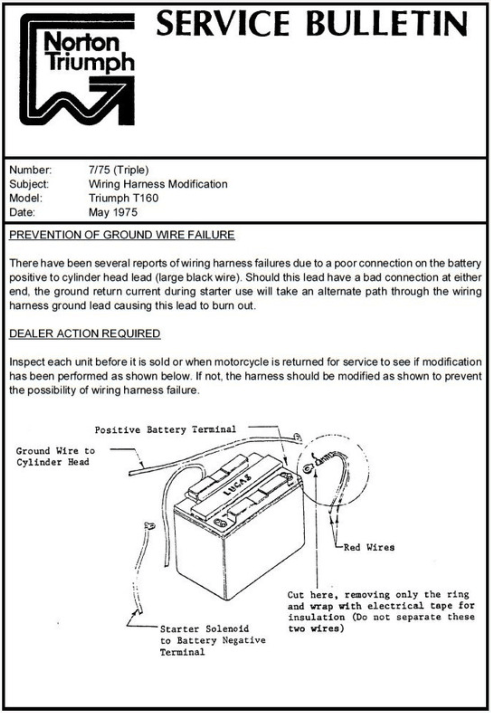
NVT had the same problem with the Triumph T160 back in the day.
They sent a Service Bulletin out to the dealers and distributors instructing them to cut the light gauge wire from the battery, leaving only the heavy one. The same thing should be done on the MK3 Commando too (there are a lot of commonalities with the electrical system on the MK3 Commando and the T160 Triumph, as they were under the same ownership by that point)
All of the MK3 diagrams here on my site have that cable deleted for this very reason.
You often see MK3’s with this cable cut. I think it is common for a new owner of a bike to wrongly reinstate this wire when they open the side cover for the first time and discover that the wire has been cut. Wrong – it’s been cut for a very good reason!!!
Install Guide
The Alton kit comes with a very well written installation guide, which you can access here:

Regulator/Rectifier

PODtronics is the reg/rec recommended by Alton, so that’s what I have drawn in the schematic.

There are four wires to connect:
| Wire Colour | Description |
|---|---|
| Yellow (x 2) | these are the AC input and pick up on the Green/Yellow and White/Green (connection can be any way round, as this is the AC side of the circuit) |
| Red | this is the Positive output and will join to the red wire if you are using existing wiring (it goes straight to the ground/earth of the frame) |
| Black | this is the Negative output (known as the hot wire) – it will pick up on the Brown/Blue wire (which goes via a fuse straight to the battery negative terminal) |
Warning Light Assimilator
The factory warning light assimilator is not compatible with most modern regulator/rectifiers and the PODtronics is no exception so it has been removed from the schematics.
Plus, there is the matter of what the WLA is actually doing, and how much use that is.
The WLA is looking purely for some AC output from the alternator stator (about 6 ½ volts AC) it is not designed for a three phase stator either.
It gives you no information about the charging (i.e., the regulator (zeners) and rectifier)
It gives you no information about the state of the battery.
Charge Warning Light

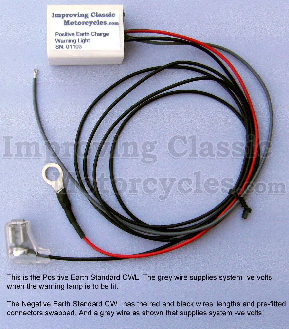
I have taken the liberty of adding an ICM Charge Warning Light to the schematics – I can certainly recommend the Improving Classic Motorcycles charge warning light as a brilliant alternative.
I use them myself, and have had a good experience with them.
The nice thing about the Improving Classic Motorcycles unit is that you can retain the original warning light – so it looks totally factory (this for me is an important factor with the MK3 with it’s quirky little instrument panel).
It gives you a lot more useful information about the state of the battery and charging system compared to the standard assimilator unit, which looks for AC output from the alternator stator only.
Diagrams
There are lots of circuit diagrams in the installation guide, which hand hold you through adding the Electric Starter kit to your bike – this is really helpful and shows superb attention to detail from the Alton guys – so kudos to them!

Another point worthy of mention is the positive feed from the battery – I mentioned it before, and I’ll say it again – there should be one heavy gauge cable from the battery positive to the back of the Alton primary case and nothing else.
The harness (i.e., the rest of the bike) receives it’s positive feed from the ring terminal on the engine side of the head steady.
The Alton diagrams suggest that the battery should have an additional lighter gauge positive feed. This is not correct.

Battery
Alton advise in their instruction manual that you should uprate the battery.
I have had good experience with Motobatt and would certainly be pleased to recommend the MBTX20UHD

This is a great choice – I really like the Motobatt AGM batteries, they seem to get through a winter layup with no problems at all.
No need to leave these on a tender over the winter, just a charge the night before your first springtime ride of the year, and you are good to go!
AGM is a sealed battery, so no worries about venting or spillage.
They are not overly expensive, and their Cold Cranking ability is good, making them a nice upgrade for electric start bikes!
1971 Norton Commando Wiring Schematic + Alton Electric Start
This is often referred to as the “Interim” model.
It is distinguishable by the three pin master switch (ignition key switch) which was Lucas part number LU39565.
These were made ONLY for the Norton Commando, and are no available as an aftermarket replacement.
If you are not comfortable rebuilding the switch, most people choose to go for the LU30552, which IS readily available.
You can find an article on ignition switches here, that may be of interest.
1971 Norton Commando Wiring Schematic + PODtronics Regulator/Rectifier PNG 5600×3960

This diagram is also downloadable as a PDF from HERE
1972 onwards Norton Commando Wiring Schematic + Alton Electric Start
The 1972 onwards schematic covers 750 and 850 bikes and has the much more familiar four pin master switch (ignition key switch)
1972 onwards Norton Commando Wiring Schematic + PODtronics Regulator/Rectifier PNG 5600×3960

This diagram is also downloadable as a PDF from HERE
Hi, Grant.
Great website and very useful. I am just rewiring a Norton Commando interstate 1972 and i have been using your guide, the machine has an Alton electric start and a Boyer ignition system. You state that only one wire to be connected to the positive terminal to the primary case , just wondering what people do with the red wire from the loom that used to connect there?
Do i cut the ring connector off and tape it up leaving the red wires still connected to each other?
Hi Mark,
Simply disconnect the ring terminal from the battery and tape it up with some insulation tape.
It is important that the red cables are connected to each other for continuity of the positive feed from front to back of the bike.
Cheers!