

Manny got in touch via the Norton Commando Facebook group, as he is in the process of working on his MK3 Commando and was looking for some help with the electrics.

There are a few ‘upgrades’ on the bike fitted by the previous owner (like a Boyer Bransden electronic ignition) but Manny has very sensibly decided to level-set, and do some more up to date upgrades.
Electronic Ignition
The new kid on the block for Electronic Ignitions is Tri-Spark.
Well, I say new kid – they have been around since about 2009.
You can find the Tri-Spark website here.

Tri-Spark get a bad press for reasons I have gone into in an article here – I have never, ever had an issue with them – always reliable, great customer service, and fully of some great features.
They are my personal preference for electronic ignitions, and I recommend them to anyone thinking of moving based on my own great experience.
The Tri-Spark unit is a one box solution – all the gubbins are mounted inside the points cover – no additional black box to try and hide under the tank, and very, very simple to connect up.
The wiring is as follows:
- Red wire – this is the positive feed to the Tri-Spark unit. Most people attach this wire to one of the two fixing posts inside the points cover. I would personally recommend running an additional red wire alongside the other two and splicing in to the red at the head steady or better still directly into the coil – I have drawn the wiring diagrams this way.
- Black/Yellow – this is the negative feed to the Tri-Spark unit. As standard, this joins in to the White/Yellow wire that used to feed the Ballast Resistor (which gets removed).
- Black/White – this is the negative supply FROM the Tri-Spark TO the coil.
Manny has gone for the dual output single tower coil from cNw – so there is no worry with moving the pair of single 6-volt coils to a series setup for wasted spark ignition as with a normal points conversion.
You’ll note in the wiring diagram below that the Ballast Resistor and Condensers have been removed as part of the conversion to Electronic Ignition – they are no longer required.
Two major benefits of the Tri-Spark:
- a very low operating voltage – as low as 8 volts means your bike will still run with a less than optimal battery and charging system
- circuitry performs the electronic equivalent of advance and retard to make the bike easier to start and stop the possibility of kick-back. This makes it gentler on your knees, and kinder to electric start systems (aka sprag clutches)
One point worthy of note with dual output single tower coil conversions is sparkplug choice.
Most people don’t realise that with this type of coil, the sparks at the sparkplugs jump the opposite way on one lead.
So for one sparkplug, the spark jumps from the centre electrode to the ground electrode (as you’d normally expect)
However, for the other sparkplug, the spark jumps from the ground electrode to the centre electrode (which is opposite to what you’d think)
Therefore, when choosing your sparkplugs, you need to bear this factor in mind!
Many people go for precious metal plugs – like platinum or iridium.
The benefit of these plugs is longevity – they simply last longer.
With the spark jumping from the ground electrode to the centre electrode, this benefit is totally lost.
The answer is to run double platinum or similar plugs, where a precious metal is used at BOTH the centre electrode AND the ground electrode.
My personal preference is the Denso VW22 plug – this has a platinum pad on the ground electrode and an iridium centre electrode.
I like Densos as they just seem to last forever – I use the IW22 on twin coil bikes, and their VW22 is the ‘twin precious metal’ equivalent.
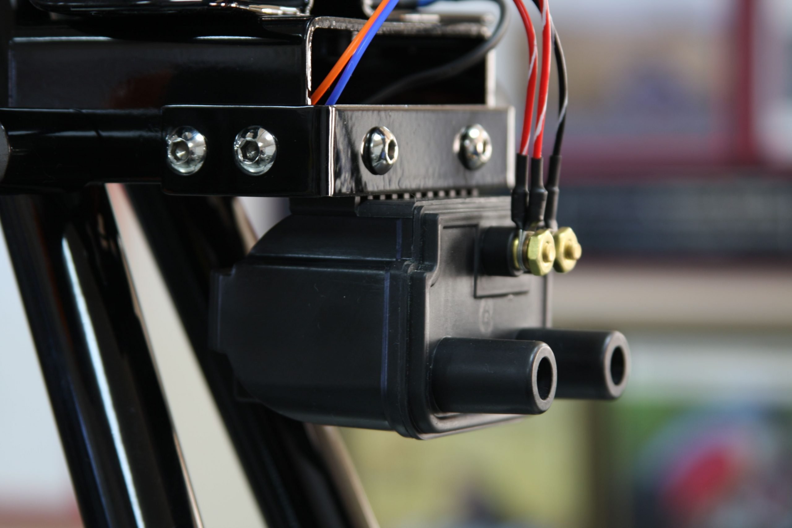
Coil
In lieu of the twin 6 volt coils, Manny has gone with the dual output single tower coil from Colorado Norton Works (it’s the brilliant Crane Cams/Dyna unit) and looks much neater.
3 phase Alternator
Manny will also be fitting a 3 phase Lucas alternator – a nice choice for superior charging in modern traffic conditions.

Regulator/Rectifier
Manny has done the usual thing and swapped in a modern regulator/rectifier in lieu of twin zener diodes and Lucas half wave silicon rectifier.
The MK3 Commandos use a Lucas half wave rectifier and two separate zener diodes on the AC side, to bring the rectification up to full wave (the zeners can be found mounted on the back of the z-plates).
The factory setup is a compromise, as it brings charging voltage down by nearly a volt compared to the previous generation of RM21 stator and single zener.
A combined regulator/rectifier replaces both zeners as well as the rectifier with one package.
Manny has gone for the new to market Tri-Spark MOSFET unit which he bought from cNw.
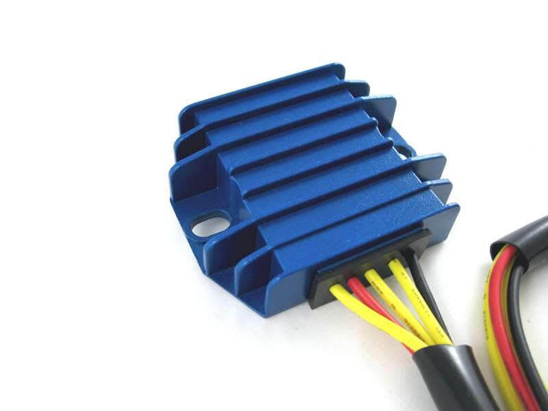
It is certainly easy to spot in it’s blue anodised heat sink!
There are five wires to connect:
- Three Yellows – these are the AC input and pick up on the three alternator stator wires – connection can be any way round, as this is the AC side of the circuit
- Red – this is the Positive output and will connect to the positive terminal on the battery.
- Black – this is the Negative output (known as the hot wire) – I like to wire it directly to the battery via it’s own dedicated 20 amp fuse.
The spec on paper is very good, being able to handle up to 20 amps.
And the benefit of MOSFET is much more precise control of the charge voltage.
Here are the wiring instructions for the Tri-Spark VR-0030 MOSFET regulator/rectifier.

Charge Warning Light
The final thing worth noting is the Charge Warning Light.
Manny has not specified this, but it is something I have added on – the factory assimilator is not reliable, and with a combined reg/rec does not work well at all.
Tri-Spark (along with Boyer Bransden with their Power Box) is one of the manufacturers that has detailed that the factory warning light assimilator is NOT supported with their reg/rec unit.
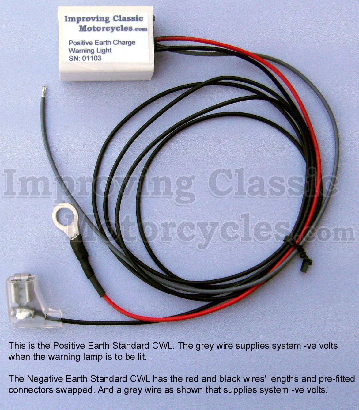
I have gone for the Improving Classic Motorcycles warning light and added it to the diagram – it is my preference, and I use it myself.

The nice thing about the Improving Classic Motorcycles unit is that you can retain the original warning light – so it looks totally factory (this for me is an important factory with the MK3 with it’s quirky little instrument panel.
It gives you a lot more useful information about the state of the battery and charging system compared to the standard assimilator unit, which looks for AC output from the alternator stator only.
Earth/Positive Feed
You will note that on the MK3 harness picture above, there is NO red + wire to the battery.
This is because there is a heavy gauge cable that from the battery positive terminal directly to the engine crankcase right next to the Prestolite electric starter motor.
It is important not to take any other connection from the main harness in to the battery on this side (the aftermarket reg/rec is different, and in a little circuit on it’s own), as if for any reason you have disconnected the heavy gauge cable (maybe you are doing some maintenance work on the primary), and you inadvertently touch the starter button, you can quite easily pull 200 amps of unfused power through the other cables in the wiring harness that are rated at 20 amps.
The wires simply melt!
NVT had the same problem with the Triumph T160 back in the day.
They sent a Service Bulletin out to the dealers and distributors instructing them to cut the light guage wire from the battery, leaving only the heavy one. The same thing should be done on the MK3 Commando too (there are a lot of commonalities with the electrical system on the MK3 Commando and the T160 Triumph, as they were under the same ownership by that point)
All of the MK3 diagrams here on my site have that cable deleted for this very reason.
You often see MK3’s with this cable cut. I think it is common for a new owner of a bike to wrongly reinstate this wire when they open the side cover for the first time and discover that the wire has been cut. Wrong – it’s been cut for a very good reason!!!
So the correct routing for the positive battery feed is:
- A single 6 gauge cable from the battery to the crankcase on the MK3
- A connection at the head steady into the rest of the wiring harness as detailed in the standard factory harness)
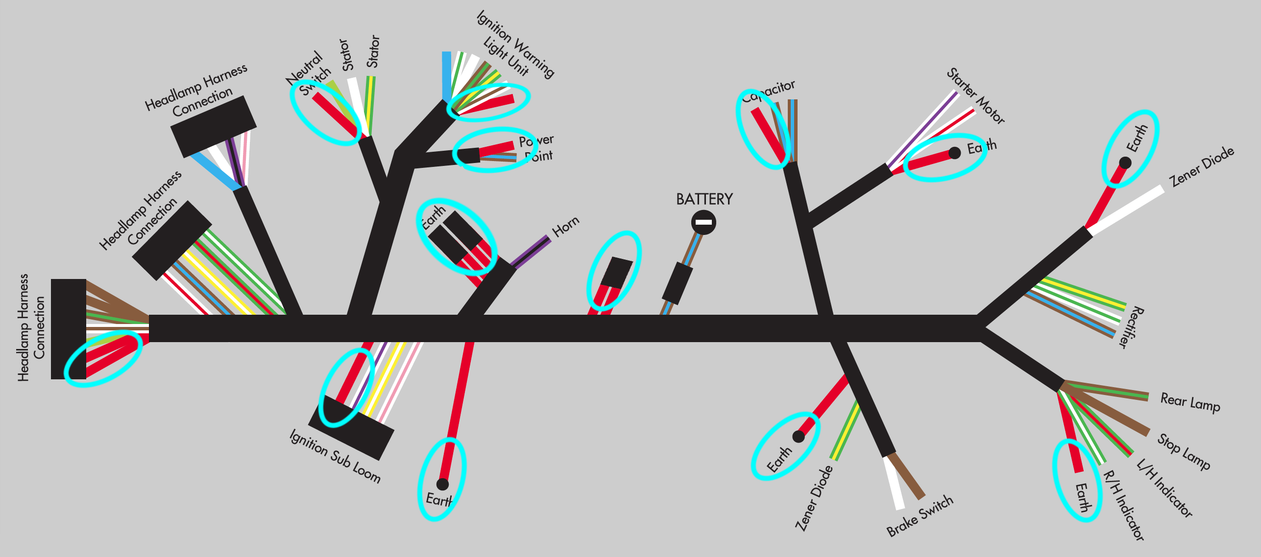
Wiring Diagram
Here is the Wiring Diagram for Manny’s bike.
Custom Norton Commando Wiring Diagram – Manny Reza PNG 3066×1841
This is also available for download as a PDF