


This is a custom wiring diagram for Luke Turner from the Access Norton Forum and Commando Facebook Group
Electronic Ignition
Luke has fitted a Boyer Bransden MK3 electronic ignition to his bike.
A really popular Norton Commando upgrade is to move from the old points-based ignition system over to Electronic Ignition.
One of the most common units of the time is Boyer Bransden, who have been around since 1969.

They are still going today, and their website can be found here.
Moving from points to Boyer electronic ignition is a pretty simple upgrade.
From a wiring perspective, the most important thing to note is that you will be moving from a pair of coils that are wired in parallel to series.
Originally, the points make and break the positive (earth) side of each coil in turn.
The Boyer electronic ignition system uses a concept called “wasted spark” – with the two coils wired in series, they are energized together on every rotation of the camshaft.
You’ll note in the wiring diagrams below that the Ballast Resistor and Condensers have been removed as part of the conversion to Electronic Ignition.
The color coding of the wiring is simple:
- The Red – this is the positive feed to the Boyer, and is usually picked up from the red wire that goes to the Coil positive terminal.
- The Black – this is the negative supply FROM the Boyer TO the coils.
- The White – this is the negative feed to the Boyer. This joins in to the White/Blue wire that used to feed the Ballast Resistor that you are removing. As standard, this goes up to the big connector block under the tank, where it’s joined to the White/Yellow that is the kill switch on your left side handlebar switch cluster.
- Black/Yellow and Black/White – these go from the Boyer black box (they call it the Transistor Box) down to the Stator Plate that sits behind the points cover.
Regulator/Rectifier
He’s also fitted a Boyer Bransden Power Box regulator/rectifier with built-in Charging Light.
This means that we need to remove the factory assimilator, and re-purpose the cabling up to the warning light in the headlamp shell.

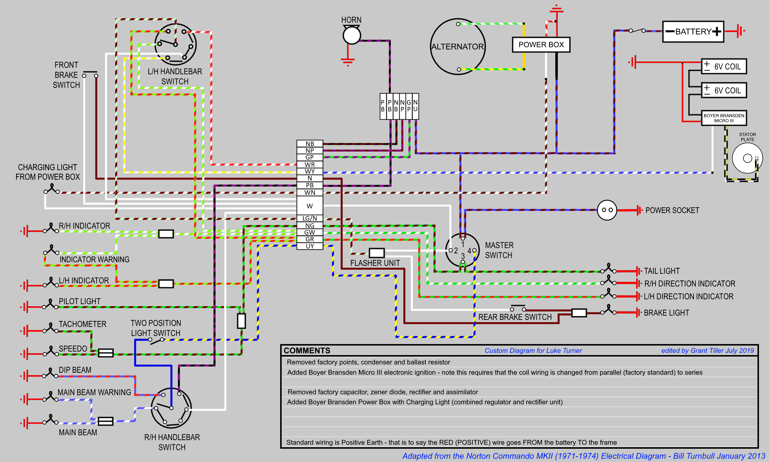
Wiring Diagram
Here is the diagram:
Custom Norton Commando Wiring Diagram – Luke Turner PNG 3066×1841
Gant Ttiller
Thank you for the modified wiring diagram you sent me for my 1971 Norton commando showing the the interface with the Boyer Bransden Power Box type PBOX0066 with charging light circuit wiring diagram, think I can now install the power box with confidence
thank you again
Mike Warner