


A popular upgrade in the late 70s and early 80s is the Lucas RITA electronic ignition system.
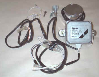
Easily spotted on the Norton Commando, the Lucas RITA needed a larger points cover to house the large “reluctor” plate.

You can find a copy of the original Lucas RITA AB11 fitting instructions here:

UPDATE
There was an earlier version of the Lucas Electronic Ignition called the AB5 – it is very similar, but the wiring colors are slightly different.
I have drawn up a set of wiring diagrams that cover the different colored cables of the AB5.
You can find it by clicking here.
Lucas RITA units are no longer in production, but a popular source for spares and repairs here in the UK is Rex’s Speedshop
1968 Norton Commando Wiring Schematic + Lucas RITA AB11 electronic ignition
These are the pre-1971 bikes and have the ammeter in the headlight shell, as well as the Wipac Triconsul type handlebar switch.
The wiring is very simple, and more like the Atlas than what came to be familiar with the Commando.
Note that I have included the Front Brake Switch as standard – this was a US requirement, that didn’t appear on the earliest UK bikes.
It is worth noting that the early bikes were fitted with 12 volt coils. These MUST be replaced for the later 6 volt coils (fitted from 1970 onwards) for Electronic Ignition to work reliably.
1968 Norton Commando Wiring Schematic + Lucas RITA AB11 electronic ignition PNG 5600×3960

This diagram is also downloadable as a PDF from HERE
1971 Norton Commando Wiring Schematic + Lucas RITA AB11 electronic ignition
This is often referred to as the “Interim” model.
It is distinguishable by the three pin master switch (ignition key switch) which was Lucas part number LU39565.
These were made ONLY for the Norton Commando, and are no available as an aftermarket replacement.
If you are not comfortable rebuilding the switch, most people choose to go for the LU30552, which IS readily available.
You can find an article on ignition switches here, that may be of interest.
1971 Norton Commando Wiring Schematic + Lucas RITA AB11 electronic ignition PNG 5600×3960

This diagram is also downloadable as a PDF from HERE
1972 onwards Norton Commando Wiring Schematic + Lucas RITA AB11 electronic ignition
The 1972 onwards schematic covers 750 and 850 bikes and has the much more familiar four pin master switch (ignition key switch)
1972 onwards Norton Commando Wiring Schematic + Lucas RITA AB11 electronic ignition PNG 5600×3960

This diagram is also downloadable as a PDF from HERE
MK3 Commando
During the manufacture of the MK3, Norton and Triumph were coming together, and they were often feeding from the same parts bins.
We have noted some anomalies between the handlebar switches while the MK3 was in production, as they frequently used the Triumph T140E switches, which look the same, but have a couple of small wiring differences.
Left handlebar switch the U (blue) used by Norton (and illustrated in the factory workshop manual) has been replaced with a UY (blue/yellow) cable. This connects to the U (blue) of the right handlebar switch inside the headlamp bucket.
Right handlebar switch there is no S (slate grey) instead, the single “hot” negative from the pin 2 of the Master Switch (ignition key switch) is jumpered for both engine run/kill switch and the starter button.


Another element of the MK3 that sometimes causes confusion is the wiring around the Warning lights.
The factory workshop manual shows the following:
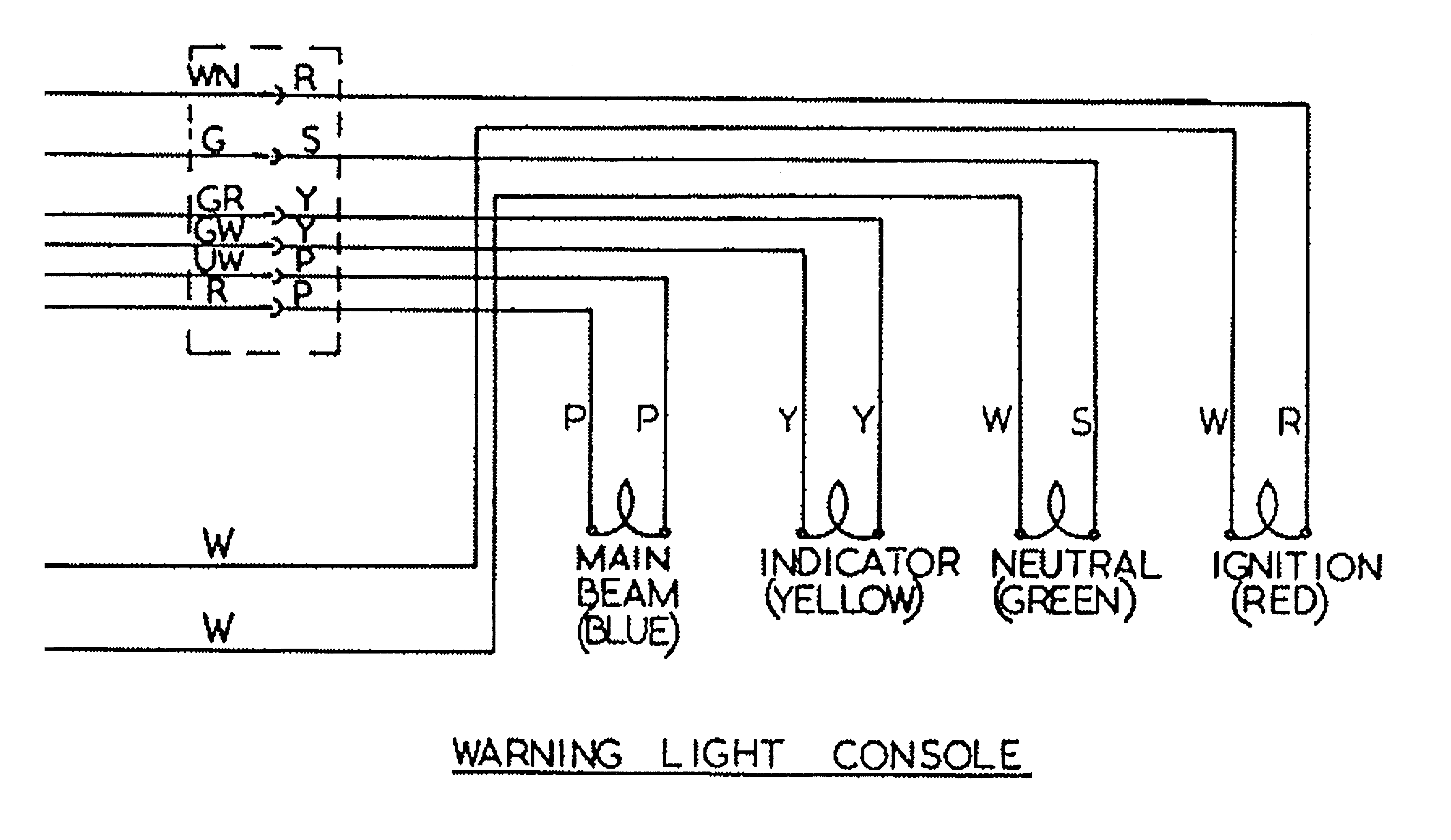
I have covered this in more detail in a separate article, which can be found here.
But in short, the cable colors used for the sub-console wiring harness were not the same all the way through MK3 production – so certainly something to watch out for!
1974 Norton MK3 Commando (Early) Wiring Schematic + Lucas RITA AB11 electronic ignition
1974 MK3 Early Bikes – there were around 2,000 bikes that were built around the December 1974 timeframe that have three additional fuses that can be found in the headlamp bucket.
These bikes are also wired with the old Lucas 3AW 3 wire ‘silver can’ assimilator.
1974 Norton MK3 Commando (Early) Wiring Schematic + Lucas RITA AB11 electronic ignition PNG 5600×3960

This diagram is also downloadable as a PDF from HERE
1975 Norton MK3 Commando Wiring Schematic + Lucas RITA AB11 electronic ignition
This is the most common configuration, and takes us through to the final Commando that rolls off the production line.
1975 Norton MK3 Commando Wiring Schematic + Lucas RITA AB11 electronic ignition PNG 5600×3960

This diagram is also downloadable as a PDF from HERE
1975 Norton MK3 Commando (Canadian Market) Wiring Schematic + Lucas RITA AB11 electronic ignition
For the Canadian Market, there were legal requirements around the headlamp being on while the engine was running.
The wiring diagram includes changes needed (swapping out the Warning Light Assimilator 06-6393 for the Headlamp Warning Unit 06-6392).
Note that a different Master Switch (ignition key switch) is also required – the key switch differences for Canada are covered here in a separate article.
This is covered in the Factory Wiring Diagram, by notes.
While the Headlamp Warning Unit is available from our friends at Andover Norton, the Canadian key switch LU30825 is not available, and must be rebuilt manually.
1975 Norton MK3 Commando (Canadian Market) Wiring Schematic + Lucas RITA AB11 electronic ignition PNG 5600×3960

This diagram is also downloadable as a PDF from HERE
NOTE:
A couple of points about the way these diagrams have been drawn:
- The diagrams on my site are schematics – the components are not drawn in the physical location on the bike. Instead they are drawn in locations that make the diagram the easiest and most logical to follow.
- Where the same colour wire goes in to and out of a single connector, that connector has usually been omitted from the drawing.
It’s obvious on the bike, is easy to spot and easy to troubleshoot.
Leaving them off the diagrams makes them a LOT easier to read, and considerably less cluttered. - Wherever the earth or ground side of a component goes back to the battery, the drawing shows a red earth symbol:

In reality, this could be connected either to a red wire in the bike’s wiring harness (loom) OR it could be attached to the frame or engine of the bike.
I have shown the red earth symbol each time in order to massively simplify the diagram, and make it a lot easier to understand for everyone.
I have also coloured them red as a gentle reminder that these bikes are wired positive earth!
1 thought on “Norton Commando Wiring Diagrams + Lucas RITA AB11”