


One of the most common upgrades or modifications for a classic british bike is to add a combined regulator/rectifier unit.
Our Commandos use a blue can capacitor, zener diode (which can be found mounted on the back of the z-plate) and rectifier unit.
A combined regulator/rectifier replaces all of these components with one package.

Boyer Bransden are a popular manufacturer of aftermarket regulator/rectifiers with their Power Box units which are available in single phase, three phase and high power versions.
However, one very important thing to note, which often gets overlooked is that the Boyer Bransden Power Box is not compatible with the Warning Light Assimilator used on the Norton Commando.
You can see in the note below:
If your Norton has a charging warning light simulator it must not be used with the
power box, remove it. If the light control is required fit the power box type
PBOX00166 with charging light control.
While the wording is poorly put, and the grammar is bad, the message is very clear.
You can see the original instructions here:
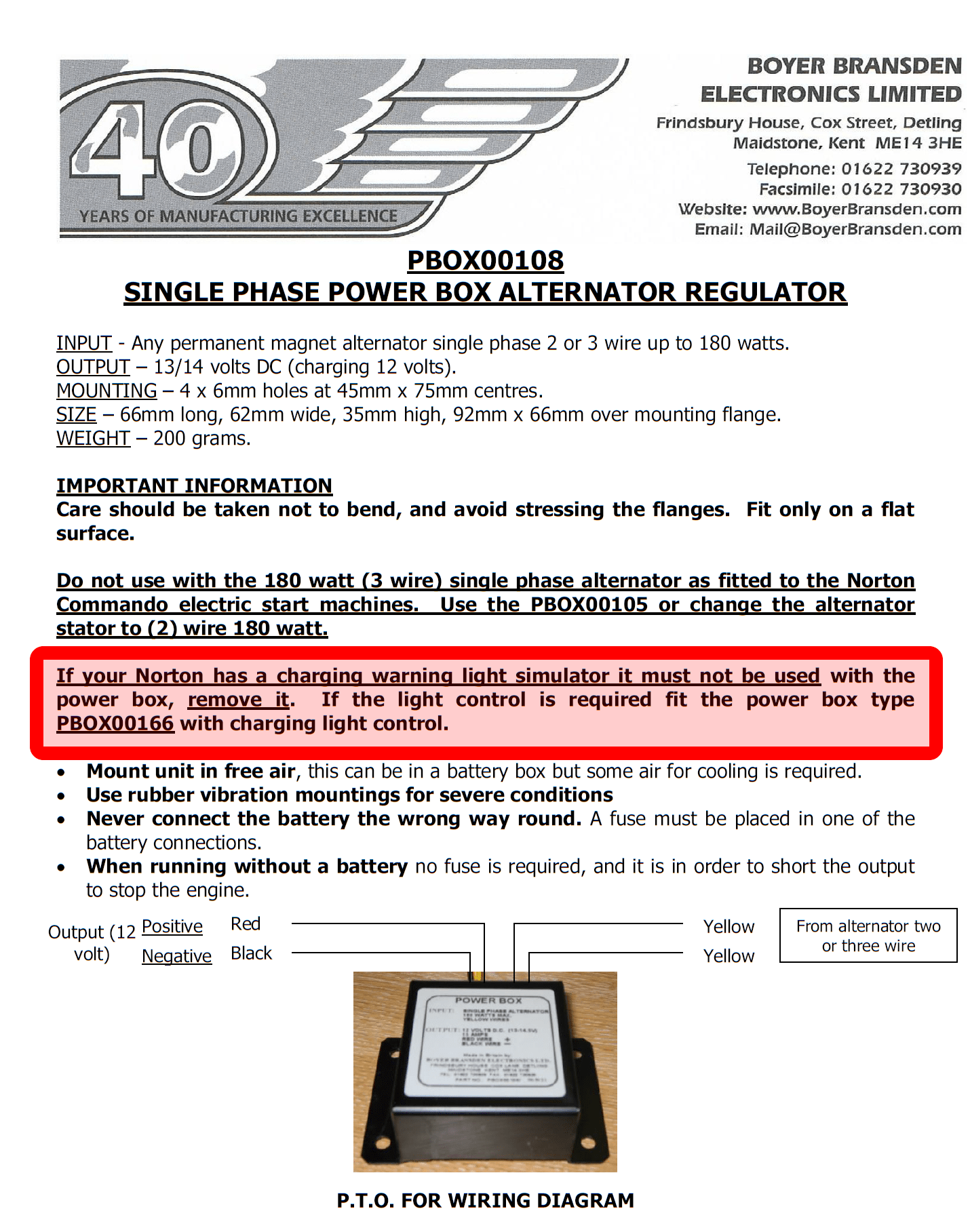
As you can see in the instructions, Boyer Bransden sell a different Power Box unit, if you want to continue and use the red warning light to show charge. It is the PBOX00166 model.
The Instructions that come with the PBOX00166 Boyer Bransden Power Box regulator/rectifier with charging light control can be found here:

There are six wires to connect:
| Wire Colour | Description |
|---|---|
| Yellow (x 2) | these are the AC inputs and pick up on the Green/Yellow and Green/White (connection can be any way round, as this is the AC side of the circuit) |
| Red | this is the Positive output and will join to the red wire if you are using existing wiring (it goes straight to the ground/earth of the frame) |
| Black | this is the Negative output (known as the hot wire) – it will pick up on the Brown/Blue wire (which goes via a fuse straight to the battery negative terminal) |
| White | this is the positive feed to the warning lamp – it is switched by the reg/rec based on the presence of an AC output from the stator |
| Red/White | this is linked in to the Red ground lead |
Note – the wiring is the same for both the Boyer Bransden Micro MKIII and Micro MKIV systems.
1968 Norton Commando Wiring Schematic + Boyer Bransden Power Box regulator/rectifier
These are the pre-1971 bikes and have the ammeter in the headlight shell, as well as the Wipac Triconsul type handlebar switch.
The wiring is very simple, and more like the Atlas than what came to be familiar with the Commando.
Note that I have included the Front Brake Switch as standard – this was a US requirement, that didn’t appear on the earliest UK bikes.
It is worth noting that the early bikes were fitted with 12 volt coils. These MUST be replaced for the later 6 volt coils (fitted from 1970 onwards) for Electronic Ignition to work reliably.
1968 Norton Commando Wiring Schematic + Boyer Bransden Power Box regulator/rectifier PNG 5600×3960

This diagram is also downloadable as a PDF from HERE
1971 Norton Commando Wiring Schematic + Boyer Bransden Power Box regulator/rectifier
This is often referred to as the “Interim” model.
It is distinguishable by the three pin master switch (ignition key switch) which was Lucas part number LU39565.
These were made ONLY for the Norton Commando, and are no available as an aftermarket replacement.
If you are not comfortable rebuilding the switch, most people choose to go for the LU30552, which IS readily available.
You can find an article on ignition switches here, that may be of interest.
1971 Norton Commando Wiring Schematic + Boyer Bransden Power Box regulator/rectifier PNG 5600×3960

This diagram is also downloadable as a PDF from HERE
1972 onwards Norton Commando Wiring Schematic + Boyer Bransden Power Box regulator/rectifier
The 1972 onwards schematic covers 750 and 850 bikes and has the much more familiar four pin master switch (ignition key switch)
1972 onwards Norton Commando Wiring Schematic + Boyer Bransden Power Box regulator/rectifier PNG 5600×3960

This diagram is also downloadable as a PDF from HERE
MK3 Commando
During the manufacture of the MK3, Norton and Triumph were coming together, and they were often feeding from the same parts bins.
We have noted some anomalies between the handlebar switches while the MK3 was in production, as they frequently used the Triumph T140E switches, which look the same, but have a couple of small wiring differences.
Left handlebar switch the U (blue) used by Norton (and illustrated in the factory workshop manual) has been replaced with a UY (blue/yellow) cable. This connects to the U (blue) of the right handlebar switch inside the headlamp bucket.
Right handlebar switch there is no S (slate grey) instead, the single “hot” negative from the pin 2 of the Master Switch (ignition key switch) is jumpered for both engine run/kill switch and the starter button.


Another element of the MK3 that sometimes causes confusion is the wiring around the Warning lights.
The factory workshop manual shows the following:
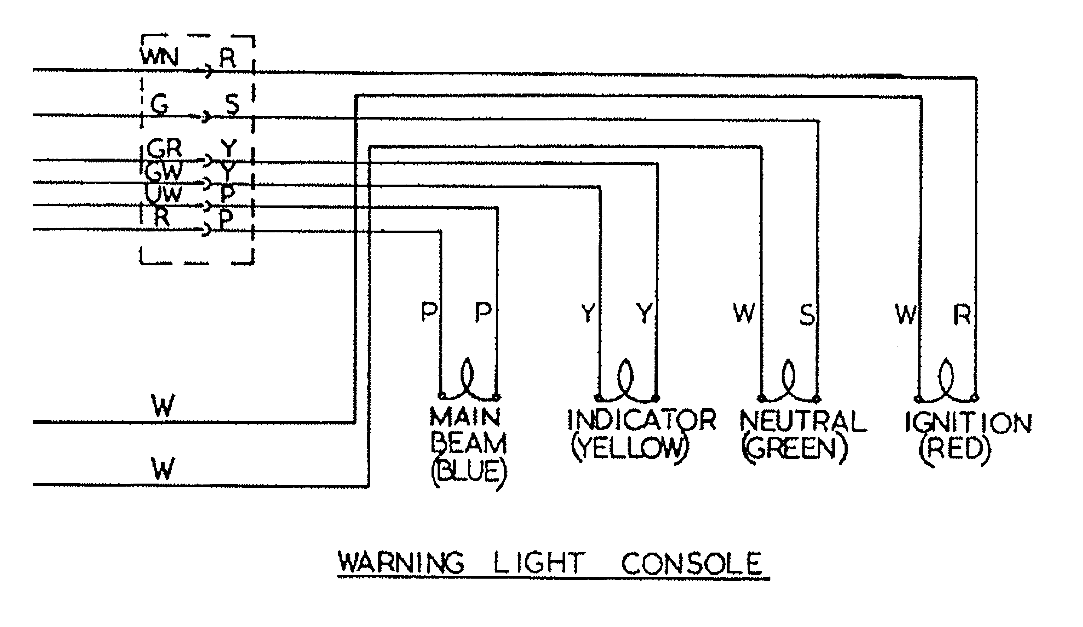
I have covered this in more detail in a separate article, which can be found here.
But in short, the cable colors used for the sub-console wiring harness were not the same all the way through MK3 production – so certainly something to watch out for!
1974 Norton MK3 Commando (Early) Wiring Schematic + Boyer Bransden Power Box regulator/rectifier
1974 MK3 Early Bikes – there were around 2,000 bikes that were built around the December 1974 timeframe that have three additional fuses that can be found in the headlamp bucket.
These bikes are also wired with the old Lucas 3AW 3 wire ‘silver can’ assimilator.
1974 Norton MK3 Commando (Early) Wiring Schematic + Boyer Bransden Power Box regulator/rectifier PNG 5600×3960

This diagram is also downloadable as a PDF from HERE
1975 Norton MK3 Commando Wiring Schematic + Boyer Bransden Power Box regulator/rectifier
This is the most common configuration, and takes us through to the final Commando that rolls off the production line.
1975 Norton MK3 Commando Wiring Schematic + Boyer Bransden Power Box regulator/rectifier PNG 5600×3960

This diagram is also downloadable as a PDF from HERE
1975 Norton MK3 Commando (Canadian Market) Wiring Schematic + Boyer Bransden Power Box regulator/rectifier
For the Canadian Market, there were legal requirements around the headlamp being on while the engine was running.
The wiring diagram includes changes needed (swapping out the Warning Light Assimilator 06-6393 for the Headlamp Warning Unit 06-6392).
Note that a different Master Switch (ignition key switch) is also required – the key switch differences for Canada are covered here in a separate article.
This is covered in the Factory Wiring Diagram, by notes.
While the Headlamp Warning Unit is available from our friends at Andover Norton, the Canadian key switch LU30825 is not available, and must be rebuilt manually.
1975 Norton MK3 Commando (Canadian Market) Wiring Schematic + Boyer Bransden Power Box regulator/rectifier PNG 5600×3960

This diagram is also downloadable as a PDF from HERE
NOTE:
A couple of points about the way these diagrams have been drawn:
- The diagrams on my site are schematics – the components are not drawn in the physical location on the bike. Instead they are drawn in locations that make the diagram the easiest and most logical to follow.
- Where the same colour wire goes in to and out of a single connector, that connector has usually been omitted from the drawing.
It’s obvious on the bike, is easy to spot and easy to troubleshoot.
Leaving them off the diagrams makes them a LOT easier to read, and considerably less cluttered. - Wherever the earth or ground side of a component goes back to the battery, the drawing shows a red earth symbol:

In reality, this could be connected either to a red wire in the bike’s wiring harness (loom) OR it could be attached to the frame or engine of the bike.
I have shown the red earth symbol each time in order to massively simplify the diagram, and make it a lot easier to understand for everyone.
I have also coloured them red as a gentle reminder that these bikes are wired positive earth!
This article is from a series of five covering Boyer Bransden products:
- Norton Commando Wiring Diagram with Boyer electronic ignition
- Norton Commando Wiring Diagram with Boyer reg/rec
- Norton Commando Wiring Diagram with Boyer electronic ignition and reg/rec
- Norton Commando Wiring Diagram with Boyer electronic ignition and three phase reg/rec
- Norton Commando Wiring Diagrams with Boyer electronic ignition – with 12 volt coils
As always don’t hesitate to reach out if you need any help or advice.
Hi! I have a 850 mk something really not very sure 1975 frame for electrical start , but have 850 ..think mk2 with drum rear brakes , I have totally overhaul it , just one issue… warning light … yes yes I know ..remove the globe…lol , new tri spark.. new lukas regulator, can’t stop warning light from flickering , it’s charging well , is there a quick easy option?? , much appreciated any input, cheers Ari
Great to hear from you Ari!
A couple of thing to note…
1) you may be confused by the behaviour of the red warning light.
By design, the light should be flickering on and off when the engine is at idle (i.e. around 1,000 – 1,100rpm)
At idle, with these alternator stators, you are not charging as much as you are taking out of the battery.
This is a really important part of the charging system design, which is often overlooked.
It is balanced so that during the course of a typical ride, you are taking out as much power as you are putting back in.
It keeps the battery in good condition, and stops the regulator from having to dump too much excess power.
2) be very careful with the standard Lucas silver can 3AW warning light assimilator.
It is not compatible with the majority of aftermarket regulator/rectifiers.
This includes the Lucas reg/rec (which is actually a rebadged PODtronics unit)
While it may appear to be working as designed, you are prematurely shortening the lift of your shiny new reg/rec.
I personally recommend the Improving Classic Motorcycles “Standard” Charge Warning Light.
This model wires in to the standard incandescent lamp, so it looks better than a modern LED.
It matches all your other warning lamps, which is particularly important on the MK3 with it’s instrument ‘console’
The ‘brainbox’ is about the size of a postage stamp, and can easily live inside the headlight bucket or under the MK3 ‘console’
Hope this helps,
Grant
Hi Grant,
Many thanks for all your work in supporting all us Norton Commando owners who aren’t capable electrians! I have looked through your wiring schematics but couldn’t find one that exactly matches my set up. I am fitting a Lucas 180W 3 phase alternator with a Boyer Bransden PBOX00105 powerbox. (no warning light assimilator facility). I also have the Boyer electronic ignition. Do you have a wiring schematic for my set up , on a 1974 850 Mk2A ?
Many thanks. Phil.
Thanks so much for your kind words Phil!
There was no page that covered the schematics for the three phase PBOX00105, so I have created one for you.
It can be found here.
Hope that helps!
Grant
Hi Grant. I hope my previous message got through – I mentioned that I am building a JPN. Is the wiring schematic you shared from Kelvin Borrow my best guidance? In terms of mounting the Boyer Bransden powerbox, I was considering locating it behind the battery, having new space with all the redundant parts. Is heat dissipation sufficient here? Is there more space under the backbone of the frame near the coils? With the JPN fairing present , neither are probably ideal ! Best regards, Phil.
Kelvin’s diagrams are bespoke, as he was starting from scratch rather than using an existing harness.
You have a standard harness as per the 1972 diagram, so stick with that.
I suggest you put the reg/rec behind the rear mudguard – that is where your cables are, so it will be nice and easy from a wiring perspective.
No advantage of putting it up front, as the fairing makes sure that air flow is almost non-existent!
Grant
Hi Grant. Thanks again for your work and providing a personalised wiring schematic! I did have a few questions…. Terminal 4 on the master switch has disappeared (light switch). Could you explain please? The redundancy parts are removed – is it okay to leave the wiring in situ? (suitably insulated). I am building the bike as a JPN, I don’t suppose you have included the JPN loom in any of your wiring schematics? The loom I have was purchased from Sprint Manufacturing when I bought the bodywork. Two Lucas 6RA relays are included to protect against current surge? Cheers, Phil.
Hi Phil,
Scroll down to the next diagram down.
For one year only, the 1971 bike was fitted with a three pin switch.
From 1972 onwards (until the end of production) a four pin switch was used.
No problem at all taping up the unused cables.
The JPN used the same main harness as the MK2a – there was a different headlamp sub harness, which accommodated the additional headlamp.
Norton used two zeners and a single phase stator on the JPN (same as the MK3)
Your choice of a three phase stator is a much, much better fit!
Hi Grant
I have an 1959 Ariel Square Four which has a Micro-Mk111 unit fitted.
The wiring was disconnected while fitting an updated “modern” alternator – +ive earth. I misplaced the diagram for reconnecting the wires …. Would there be any change going from -ive to +ive earth?
Thanks
Hi there,
Yes the wiring is different when you swap a Boyer ignition from negative earth to positive earth.
I have mapped them out for you side by side, so you can see the differences
Click here for a comparison.
Hope this helps,
Grant