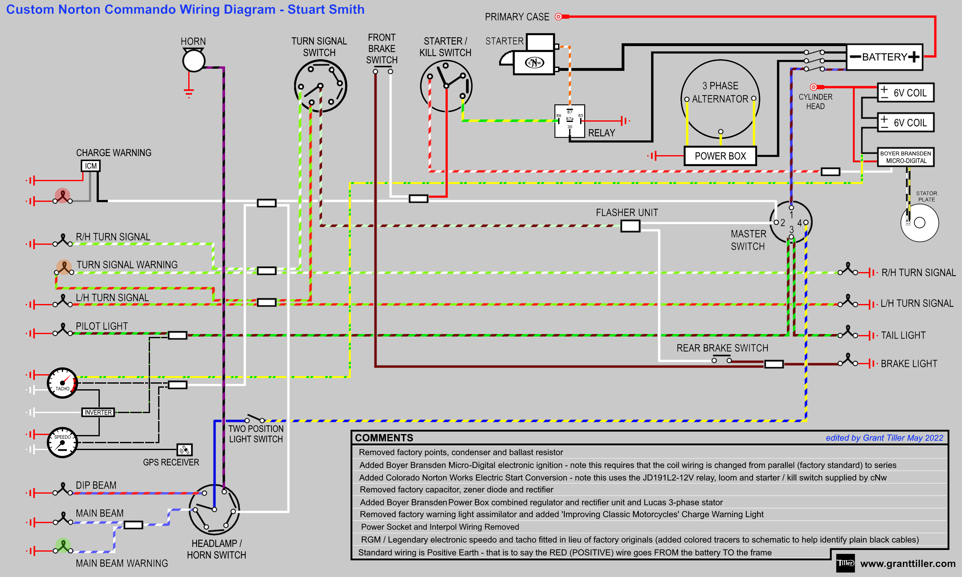
Stuart Smith reached out to me on Facebook and requested some guidance with a rewire he is doing on his 1973 Commando.
This diagram took me quite some hours, as there are lot of elements to it, and it was a challenge finding space to put everything on the page while still keeping it logical and easy to read.
I think I got there though, and hope to have done Stuart’s bike justice!
Electronic Ignition

A really popular Norton Commando upgrade is to move from the old points-based ignition system over to Electronic Ignition.
One of the most common units of the time is Boyer Bransden, who have been around since 1969.

They are still going today, and their website can be found here.
Moving from points to Boyer electronic ignition is a pretty simple upgrade.
From a wiring perspective, the most important thing to note is that you will be moving from a pair of coils that are wired in parallel to series.
Originally, the points make and break the positive (earth) side of each coil in turn.
The Boyer electronic ignition system uses a concept called “wasted spark” – with the two coils wired in series, they are energized together on every rotation of the camshaft.
You’ll note in the wiring diagrams below that the Ballast Resistor and Condensers have been removed as part of the conversion to Electronic Ignition.
The color coding of the wiring is simple:
| Wire Colour | Description |
|---|---|
| Red | this is the positive feed to the Boyer, and is usually picked up from the red wire that goes to the Coil positive terminal |
| Black | this is the negative supply FROM the Boyer TO the coils |
| White | this is the negative feed to the Boyer – it joins in to the Red/White wire on the cNw kill switch. |
| Black/Yellow and Black/White | these go from the Boyer black box (they call it the Transistor Box) down to the Stator Plate that sits behind the points cover. |
Stuart has gone for the Boyer Bransden Micro-Digital, which is a slightly enhanced version of the MKIII or MKIV you normally find.
They are usually (but not always) distinguishable by the fact that the transistor box is red instead of black.
The Micro-Digital model offers better control over ignition coil energy, starting speed, and tickover stabilisation.
Here is the installation manual for the Boyer Bransden Micro-Digital system (KIT0084)

Regulator/Rectifier
Stuart currently has a Boyer Bransden Power-Box regulator/rectifier fitted, which is fed from a three phase Lucas alternator.
The Power-Box does not support the Lucas silver can assimilator, so it is necessary to remove it.
There are five wires to connect:
| Wire Colour | Description |
|---|---|
| Yellow (x 3) | these are the AC input and pick up on the three wires coming out of the three phase alternator stator (connection can be any way round, as this is the AC side of the circuit) |
| Red | this is the Positive output and will join to one of the red wires in the harness |
| Black | this is the Negative output (known as the hot wire) – I have shown it wired directly to the battery negative terminal via it’s own dedicated fuse |

Here is the installation manual for the Boyer Bransden three phase Power-Box (PBOX105)
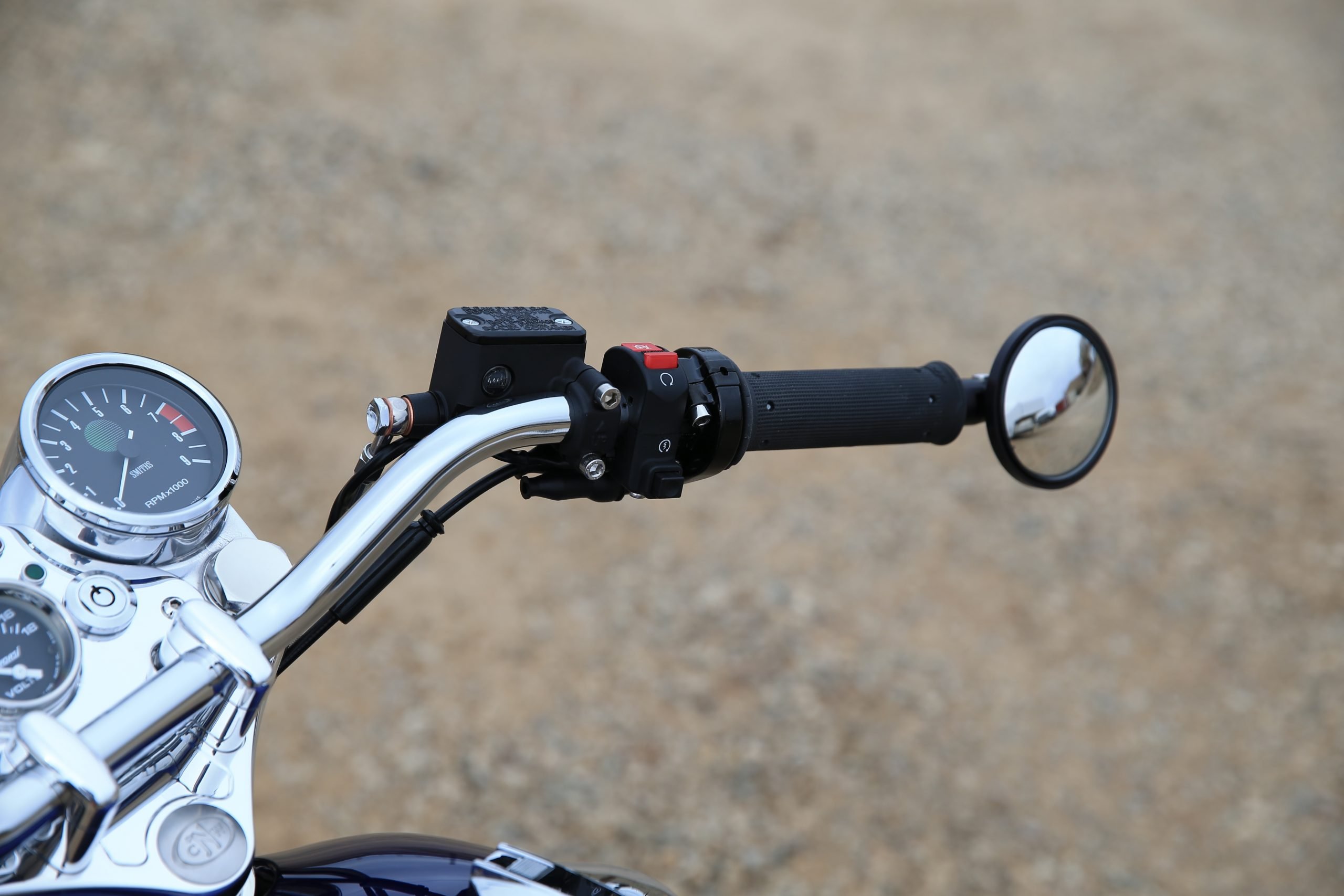
Electric Starter

Matt Rambow and his team at Colorado Norton Works make some beautiful stuff, and their Electric Start Conversion for the pre-MK3 Norton Commando is no exception.
The cNw kit, found here is actually very reasonably priced at $2,795 if you consider that it includes a belt drive primary.
The pics are from Matt’s site (not Stuart’s bike)

As always with Colorado Norton Works, the quality of the fit and finish is second to none.
If you don’t want a highly polished finish, there are options for satin and matt black too.

Matt supplies a starter button with his kit, as the quality of the original switches were dubious when they were new. That makes it difficult for Matt to support, and guarantee the reliability, hence shipping his own.
Stuart has gone ahead and fitted the replacement starter switch – I have taken the liberty of re-routing the kill switch here too in the diagram, away from the original Lucas switch.
Digital Instruments
Stuart has chosen to fit the aftermarket digital Speedo and Tacho that are made by Speedhut and sold by Legendary Motorcycles and RGM.


These are superb – especially the Speedo, as it is a GPS unit, which makes it really easy to setup – no need to play with sensors on the back wheel!
The wiring for these is not complicated, but it is a little messy – too many plain black wires can make it confusing, so I have taken the liberty of showing some colored tracers on the wiring diagram, to make it easier to follow.
Because the same gauge internals can be used in a car, you can control the dial back lighting and pointer lighting independently – again this means there are more cables to play with than is ideal, but it’s not complicated.
Here is the installation manual for the Speedhut GPS Digital Speedo
Here is the installation manual for the Speedhut Digital Tacho
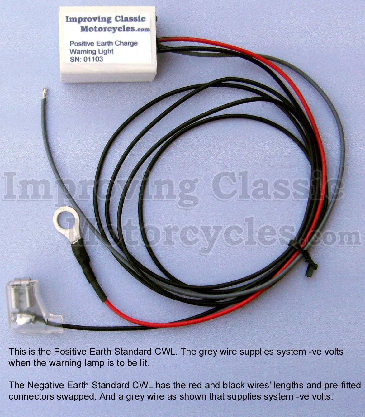
Charge Warning Light
As I mentioned, the Boyer Bransden Power-Box is one of the manufacturers that has detailed that the factory warning light assimilator is NOT supported with their reg/rec unit.
I can certainly recommend the Improving Classic Motorcycles charge warning light as a brilliant alternative.
I use them myself, and was pleased that Stuart said he is using one on his bike.

The nice thing about the Improving Classic Motorcycles unit is that you can retain the original warning light – so it looks totally factory (this for me is an important factory with the MK3 with it’s quirky little instrument panel.
It gives you a lot more useful information about the state of the battery and charging system compared to the standard assimilator unit, which looks for AC output from the alternator stator only.
Wiring Diagram
Here is the Custom Wiring Diagram for Stuart’s Commando.
Custom Norton Commando Wiring Diagram – Stuart Smith PNG 3066×1841
This is available as a PDF too – it can be downloaded here.