
Klaus Völmle recently reached out, as he was looking for some help with a wiring diagram for his 1966 Triumph Tiger T100SC.

I helped Klaus previously with his 1973 Commando, as he wanted to wire it for Negative Earth.
You can see the post here:
Custom Norton Commando Wiring Diagram – Klaus Völmle
Klaus is going for a positive earth setup for his Tiger, which he is rebuilding from a box of bits… sounds like a fun project!
It is worth noting that many of the components used here are not necessarily Klaus’s first choice – but he is using them, as they came in the box of bits with the bike.
The T100SC was Triumph’s stripped down, high piped Scrambler model, and is quite unusual.
There were many iterations of wiring for this bike at around this time, as it was a ‘factory special’ it never quite matched the mass production regular road going machine.
Charging

One of the most common upgrades or modifications for a classic british bike is to add a combined regulator/rectifier unit.
It makes great sense to do this on Klaus’s T100SC if nothing else, but for the sake of simplicity!
The bike would have originally had an ET charging system, switching in and out stator windings as you turn on and off the lights on the bike.
Actually this was a genius idea from Lucas, but it does make for a lot of wiring and a complex ignition switch/light switch combo.
By going for a PODtronics combined regulator/rectifier and a regular Lucas RM21 two wire, single phase stator, it keeps the wiring very, very simple indeed!
Podtronics are by far the most popular manufacturers of aftermarket regulator/rectifiers.

There are four wires to connect:
| Wire Colour | Description |
|---|---|
| Yellow (x 2) | these are the AC input and pick up on the Green/Yellow and Green/White (connection can be any way round, as this is the AC side of the circuit) |
| Red | this is the Positive output and will join to the red wire if you are using existing wiring (it goes straight to the ground/earth of the frame) |
| Black | this is the Negative output (known as the hot wire) – it will pick up on the Brown/Blue wire (which goes via a fuse straight to the battery negative terminal) |
Ignition

Klaus has got a Sparx electronic ignition system to fit to his bike.
These are popular among Triumph owners, as Sparx was a brand put together by Tricor Andy (Andy Gregory) the well known Triumph parts specialist.

The setup of the Sparx electronic ignition will be familiar to most.
Moving from points to the Sparx electronic ignition is a pretty simple upgrade.
From a wiring perspective, the most important thing to note is that you will be moving from a pair of coils that are wired in parallel to series.
Originally, the points make and break the positive (earth) side of each coil in turn.
The Sparx electronic ignition system uses a concept called “wasted spark” – with the two coils wired in series, they are energized together on every rotation of the camshaft.
You’ll note in the wiring diagrams below that the Ballast Resistor and Condensers have been removed as part of the conversion to Electronic Ignition.
The color coding of the wiring is simple:
| Wire Colour | Description |
|---|---|
| Red | this is the positive feed (earth/ground) to the Sparx, and is usually picked up from the red wire that goes to the Coil positive terminal |
| Black | this is the negative supply FROM the Sparx TO the coils |
| White | this is the negative feed to the Sparx. In this case, we are joining it in to Pin 2 on the Master Switch (ignition key switch) |
| Black/Yellow and Black/White | these go from the Sparx ‘Igniter Box’ down to the Stator Plate in lieu of the old points |
For your information, here is a copy of the instructions that are supplied with the Sparx unit:

Master Switch
Klaus has a 3 position Master Switch (ignition key switch)
From what I can research, these were used on Triumphs for one year only (same as with the Norton Commando) prior to being replaced by the more common four position switch.
The Lucas part number of the 3 position switch is LU39565
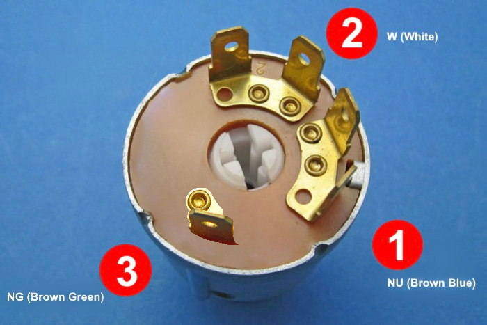
Wiring for the switch is as follows:
| Terminal Number | Wire Colour | Description |
|---|---|---|
| 1 | NU (brown/blue) | negative feed from the battery (via the fuse) |
| 2 | W (white) | switched hot negative |
| 3 | NG (brown/green) | switched negative feed to lighting circuits |
So the key positions will be as follows:
| Switch Position | Description |
|---|---|
| 1 | Off |
| 2 | Ignition |
| 3 | Ignition + Lights |
In switch position 3 (Ignition + Lights) – the pilot light and tail light will be lit in this position.
Klaus will then have a two position (on/off) Lucas toggle switch in the headlamp shell to turn the headlamp on and off.
Handlebar Switch
Just a reminder – this was not Klaus’s choice!
Actually no better or worse than the Lucas switches of the time, Klaus found in his box of parts a Yamaha SR500 handlebar switch to use.
…this is actually one of the better, more sympathetic switches available, and puts everything that is needed within easy reach on the left hand.

These were used on many bikes of the time (mainly Honda and Yamaha) so hopefully I have got the wiring colours of the switch right, based on what Klaus has got.
I have gone for the Yamaha colours, but the Honda ones were slightly different.
| Wire Colour | Description |
|---|---|
| Pink | negative to horn |
| Black | negative from ignition switch |
| Brown/White | negative from flasher unit |
| Dark Brown | left turn signal |
| Dark Green | right turn signal |
| Blue/Yellow | switched negative from two position toggle switch |
| Light Green | dipped beam |
| Yellow | main beam |
Oil Pressure/Charge Warning Light
A worthwhile upgrade that is worth it’s weight in gold is adding a Charge Warning Light in lieu of the standard warning light assimilator.

The nice thing about the ‘standard’ Improving Classic Motorcycles unit is that you can retain the original warning light – so it looks totally factory.
They also sell a ‘deluxe’ version which includes and LED
These units give you a lot more useful information about the state of the battery and charging system compared to the standard assimilator unit, which looks for AC output from the alternator stator only.
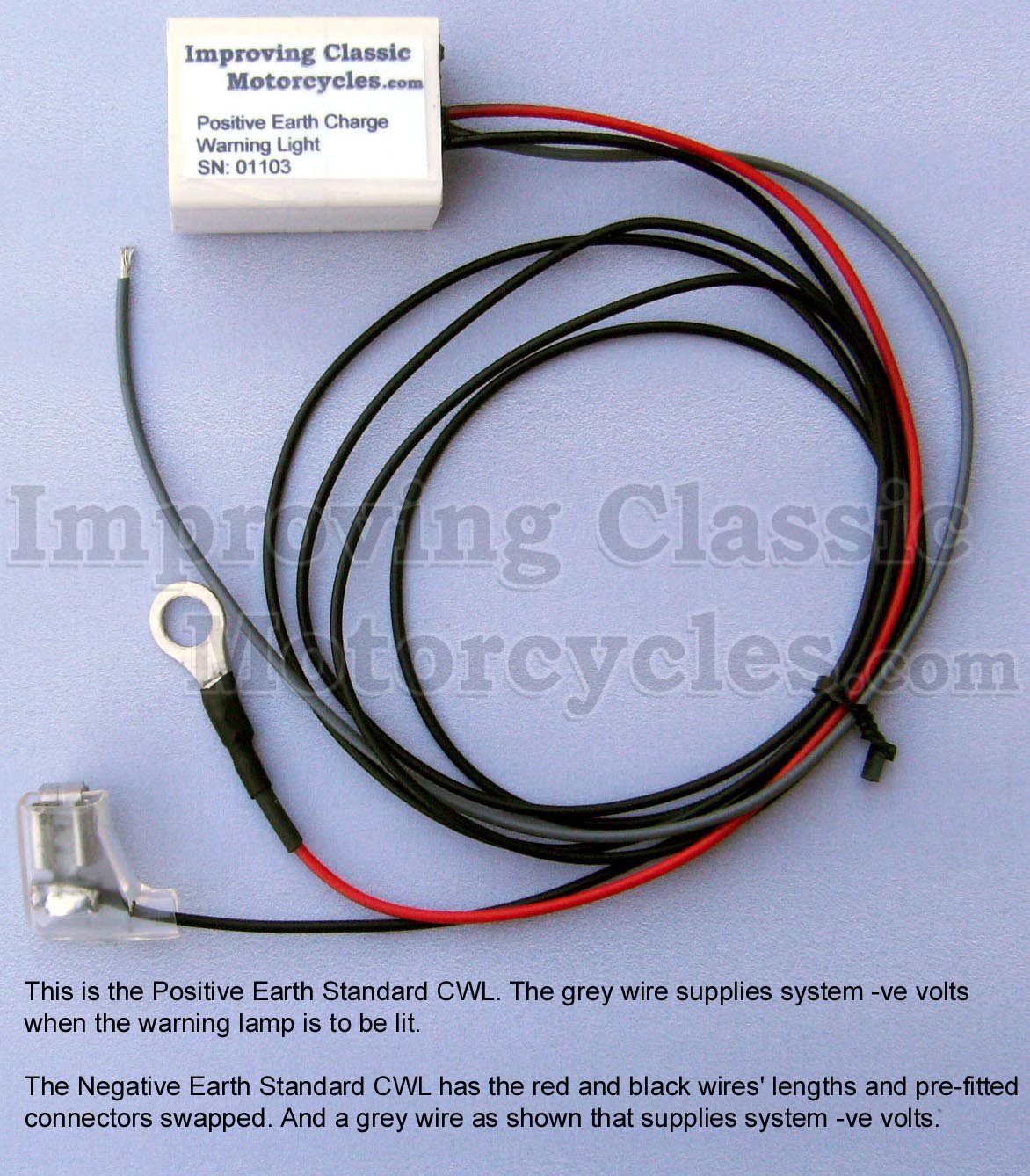
Klaus has gone one stage further, and got the version which includes and extra wire for an oil pressure switch.
I think this is a superb idea!
Wiring Diagram
Here is the wiring diagram for Klaus’s 1966 Triumph Tiger T100SC.
Klaus Völmle – 1966 Triumph Tiger T100SC Custom Wiring Diagram PNG 3066×1841
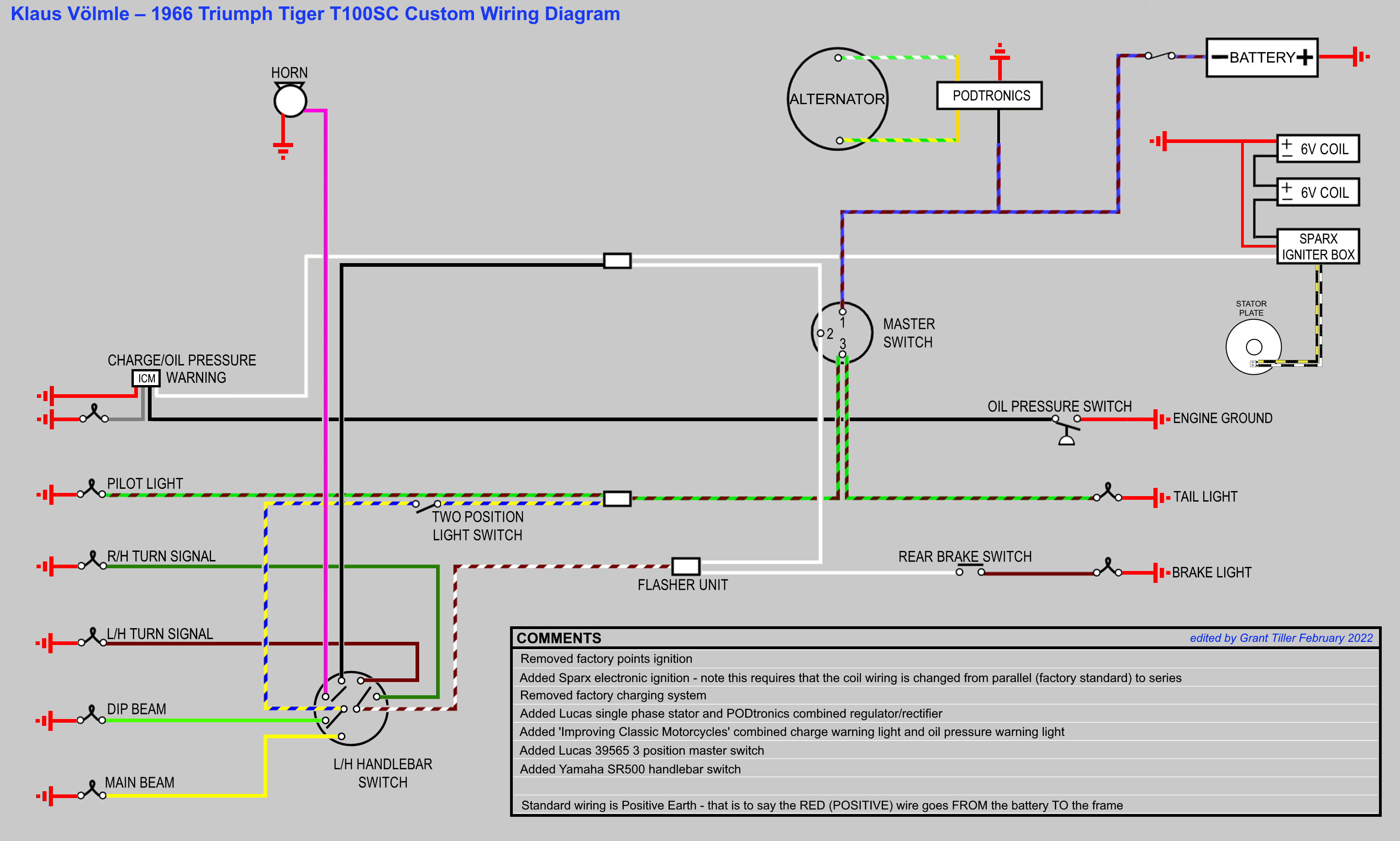
This is available as a PDF too – it can be downloaded here.
Great work, Grant!
You have my respect and thanks.
Regards, Klaus