


Richard Mattrass is based out of small town called La Conner which is in Skagit County, Washington State
Richard got a 1971 Roadster just before Christmas 2021 – surely the best kind of Christmas Present!


Since then, Richard has been fettling the bike to bring it up to date with some sympathetic reliability upgrades and some new wiring.
Electronic Ignition

A decent Norton Commando upgrade is to move from the old points-based ignition system over to Electronic Ignition.
Richard has fitted a unit that seems really popular these days – the Pazon Sure-Fire

These are popular for two reasons:
- COST – the are one of the lowest price units available on the market at the moment, and the come with an amazing seven and a half year warranty!!!
- RELIABILITY – people are nervous of the ‘shake and bake’ units like the Tri-Spark, where everything is all in one single, miniaturised unit behind the points cover. The Pazon is a carbon copy of the Boyer Bransden unit with a stator plate (Pazon call it the Ignition Trigger) and a separate box of electronics (which Pazon call the Ignition Module)


In fact, the similarities with the Boyer Bransden units don’t end there – all the wires are the same color too!
Actually, Andy and Debbie from Pazon both used to work for Boyer Bransden!!!
Moving from points to a Pazon Sure-Fire electronic ignition is a pretty simple upgrade.
From a wiring perspective, the most important thing to note is that you will be moving from a pair of coils that are wired in parallel to series.
Originally, the points make and break the positive (earth) side of each coil in turn.
The Pazon electronic ignition system uses a concept called “wasted spark” – with the two coils wired in series, they are energized together on every rotation of the camshaft.
You’ll note in the wiring diagrams below that the Ballast Resistor and Condensers have been removed as part of the conversion to Electronic Ignition.
The color coding of the wiring is simple:
- The Red – this is the positive feed to the Pazon, on a negative earth bike, this is picked up from the WU (white/blue) which becomes WY (white/yellow) at the big connector block under the tank. This is the wire that is linked to the kill switch (push to break) on the handlebars.
- The Black – this is the negative return between the Pazon and one of the coils.
- The White – this is the negative return from the Pazon to earth.
- Black/Yellow and Black/White – these go from the Pazon Ignition Module down to the Ignition Trigger that sits behind the points cover.
Regulator/Rectifier

Richard has gone for the A REG 1 combined regulator/rectifier.
This is designed and sold by Alan Osborn of AO Services
Alan is famous in Norton circles – being the Norton Owner’s Club Electrical Guru.
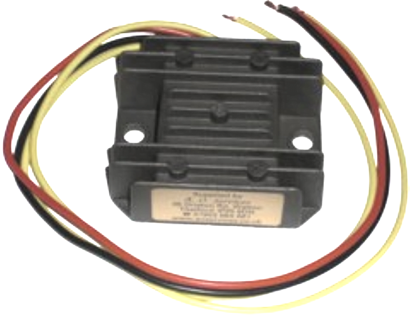
Here is the instruction sheet which comes with the A REG 1 combined regulator rectifier unit:

Warning Light Assimilator
The Lucas 3AW 3 wire ‘silver can’ assimilator is the most unreliable part of the bike in my opinion.
Think of the old-fashioned mechanical bi-metallic strip that is part of the thermostat on an old central- heating system – it’s basically the same sort of technology used here. Warming up and expansion/contraction of different metals to open and close contacts.
Couple that to a rattly, vibrating motorcycle, and you can suddenly understand why they were not wholly reliable.
Plus, there is the matter of what they are actually doing, and how much use that is.
The 3AW is looking for about 6 ½ volts coming out of the alternator stator.
It gives you no information about the charging (i.e., the regulator (zener) and rectifier)
It gives you no information about the state of the battery.
To this end, Richard has turned to fellow Norton Owners Club member (and Electrical subject matter expert) Al Osborn from A.O. Services once again!
Al has a battery status monitor available, which replaces the standard assimilator.
It has two wires:
- positive, which will tie in on the positive feed ‘BUS’
- negative, which is picked up as the W (white) from pin 2 of the ignition switch
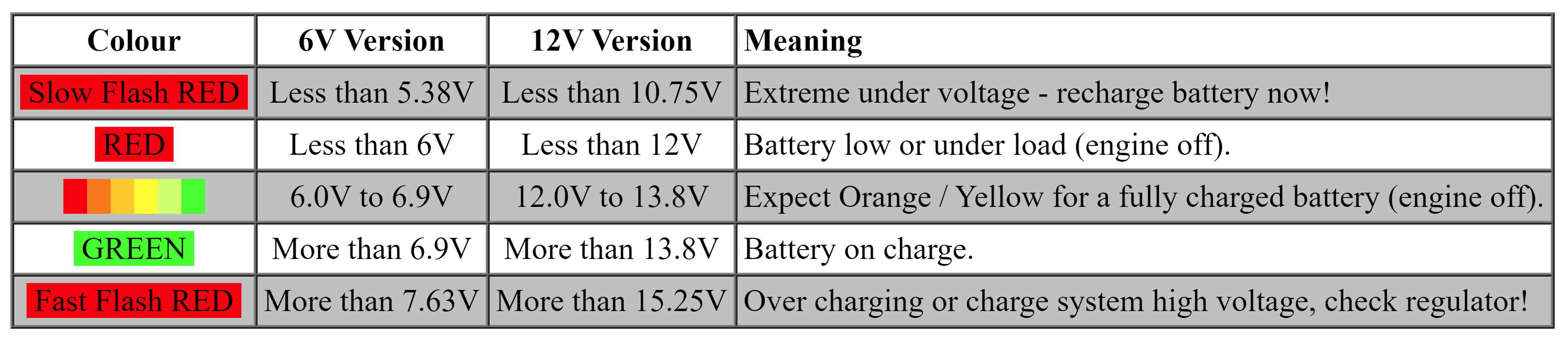
This provides you with a lot of far more useful information than the standard 3AW provides, plus it is solid state so is far more reliable.
Positive Feed
One thing I like to do, and highly recommend that others do when making your own harness is use this as an opportunity to sort out earths (in our case the positive feed) once and for all.
With the Commando, Norton (and Lucas) were innovative in that there was no reliance on the frame as a ground for the majority of the components on the bike – for example, although the original zener diode sunk it’s heat to ground on the nice, chunky heat dissipating aluminium z-plate, and the component operated by electrically connecting via it’s mounting stud, there was still a ring terminal and a red cable on the back of it – I have gone into more detail about that in an article here.
The downside in the way Norton did it is that in many of the cases, each component has a positive loop – so there are two red cables going to it – look at it as an ‘in’ and an ‘out’ – if the cable breaks at the connector, or one of the connectors becomes unplugged, it can interrupt the positive feed to the rest of the bike.
If I am building a harness from scratch, I like to run a heavier gauge positive cable from the front to back of the bike, then tap in for a feed to each component as required – there is a massive advantage in doing this, and making it part of the loom, as it means you rule out any unreliability associated with bad earths, or trying to get power through rust, paint, powder coating, paper gaskets, loctite, clutch cables, steering bearings and speedo/tacho drives.
For the sake of spending an hour running this cable now, it means you rule out a massive variable, and make troubleshooting really easy in the future. So well worth doing in my opinion!
When you splice into the cable to feed the positive to an individual component, you can use a lighter gauge cable that is rated for the maximum current that particular part will draw.
For example, the turn signals can have an 18-gauge cable – 1mm² will handle 8.75 amps and be more than enough.
Those old 21-watt lamps used in the turn signals will draw no more than 3.5 amps.
Tidy Up
Of course a few things went in lieu of the above upgrades.
The ballast resistor and condensers went when the new Electronic Ignition was added.
The zener diode, full wave silicon rectifier, and blue-can capacitor were discarded to make way for the new A REG 1 combined regulator/rectifier.
Richard has also chosen to remove the power socket and superfluous Interpol wiring as well as minimise the number of connectors under the tank where possible.
This has made for a nice, simple and uncluttered wiring harness!
Wiring Diagram

Here is the Wiring Diagram for Richard’s bike.
Custom Norton Commando Wiring Diagram – Richard Mattrass PNG 3066×1841

This is also available for download as a PDF
Thanks Richard. Any suggestions on wire gauge size?
Hi Chris,
The cable types I use on our bikes are mainly:
Thin Wall Cable
32/0.20, 1.0mm², 16.5A – cable OD 2.0mm
28/0.30, 2.0mm², 25.0A – cable OD 2.7mm
These are available in the colour ways that match our bikes harnesses.
Hope this helps,
Grant