Thomas Maurer reached out to ask for the files I used to create the negative earth wiring diagram for Klaus Völmle‘s bike as his negative earth Commando is wired in a similar way, and he wanted to make one or two changes.
I don’t use anything special to create these diagrams by the way – it is just a png file that I create and edit using the free paint.net application.
The diagram size I have as a master is 3066 x 1841 pixels in size – the exact same size and quality that is available on this website. I chose this size mainly for my US friends – it is almost perfect to print out on “Legal” size paper which is 14 x 8.5 inches
I wanted to use Canvas and was set to buy it when I first started creating these, however during my free trial, I found a major issue when it came to resizing and moving objects, in that they didn’t stay in proportion when shifting them around on screen. This was a major showstopper for me, as wires would no longer join up if I moved them!
I called it in to their technical support people, with a video and information about how to replicate the error, and they agreed it was indeed a code issue. However, that was it from their side, no further communication and no commitment to fix it. So that’s where I left the idea of using Canvas.
Anyway, I digress – let’s get back to Thomas Maurer!
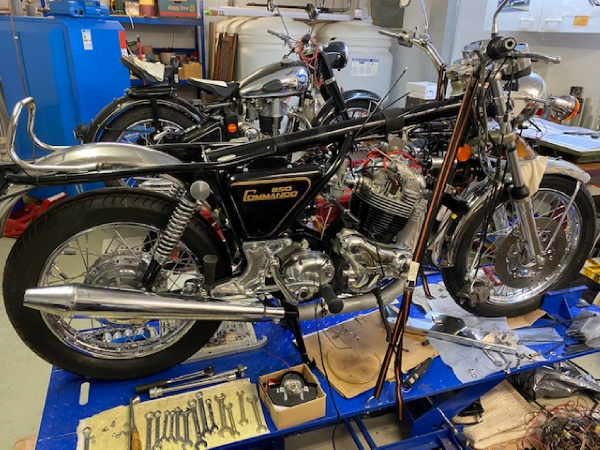
Thomas’s bike is wired for Negative Earth.
Going for negative earth is not a simple case of swapping around the battery terminals.
Thomas has Electronic Ignition, a combined regulator/rectifier and a charge warning light – all of which must be rewired in order to accommodate the change.
Ignition
A decent Norton Commando upgrade is to move from the old points-based ignition system over to Electronic Ignition.
Thomas has fitted a unit that seems really popular these days – the Pazon Sure-Fire

These are popular for two reasons:
- COST – the are one of the lowest price units available on the market at the moment, and the come with an amazing seven and a half year warranty!!!
- RELIABILITY – people are nervous of the ‘shake and bake’ units like the Tri-Spark, where everything is all in one single, miniaturised unit behind the points cover. The Pazon is a carbon copy of the Boyer Bransden unit with a stator plate (Pazon call it the Ignition Trigger) and a separate box of electronics (which Pazon call the Ignition Module)


In fact, the similarities with the Boyer Bransden units don’t end there – all the wires are the same color too!
Actually, Andy and Debbie from Pazon both used to work for Boyer Bransden!!!
Moving from points to a Pazon Sure-Fire electronic ignition is a pretty simple upgrade.
From a wiring perspective, the most important thing to note is that you will be moving from a pair of coils that are wired in parallel to series.
Originally, the points make and break the positive (earth) side of each coil in turn.
The Pazon electronic ignition system uses a concept called “wasted spark” – with the two coils wired in series, they are energized together on every rotation of the camshaft.
You’ll note in the wiring diagrams below that the Ballast Resistor and Condensers have been removed as part of the conversion to Electronic Ignition.
The color coding of the wiring is simple:
- The Red – this is the positive feed to the Pazon, on a negative earth bike, this is picked up from the WU (white/blue) which becomes WY (white/yellow) at the big connector block under the tank. This is the wire that is linked to the kill switch (push to break) on the handlebars.
- The Black – this is the negative return between the Pazon and one of the coils.
- The White – this is the negative return from the Pazon to earth.
- Black/Yellow and Black/White – these go from the Pazon Ignition Module down to the Ignition Trigger that sits behind the points cover.
Regulator/Rectifier
Another of the most common upgrades or modifications for a classic british bike is to add a combined regulator/rectifier unit.
Our Commandos use a blue can capacitor, zener diode (which can be found mounted on the back of the z-plate) and rectifier unit.
A combined regulator/rectifier replaces all of these components with one package.
The most common manufacturer of these is Podtronics and Thomas has gone for the three phase version.
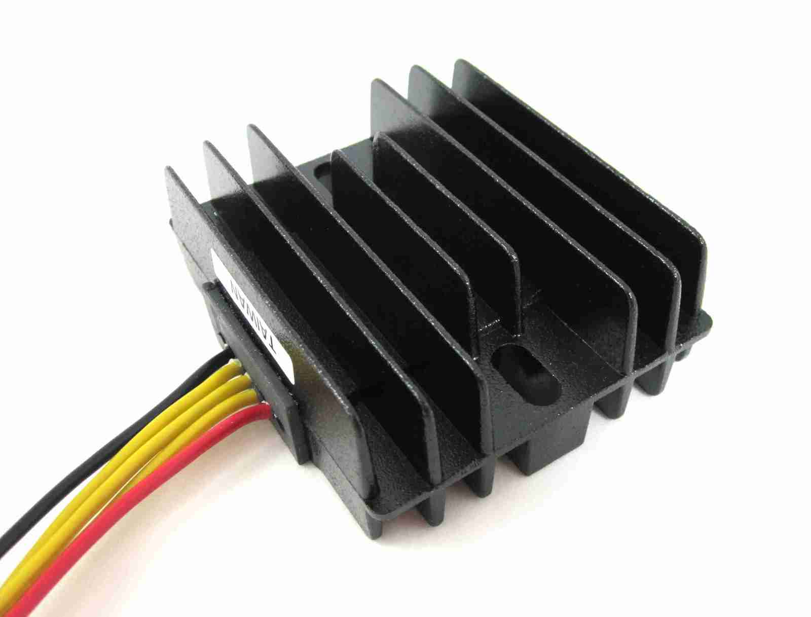
There are five wires to connect:
- Three Yellows – these are the AC input and pick up on the three wires that come from the alternator stator. The connection can be any way round, as this is the AC side of the circuit, so polarity is not important.
- The Red – this is the Positive output and will join to the positive battery terminal via it’s own dedicated fuse.
- The Black – this is the Negative output which goes to the battery negative terminal.
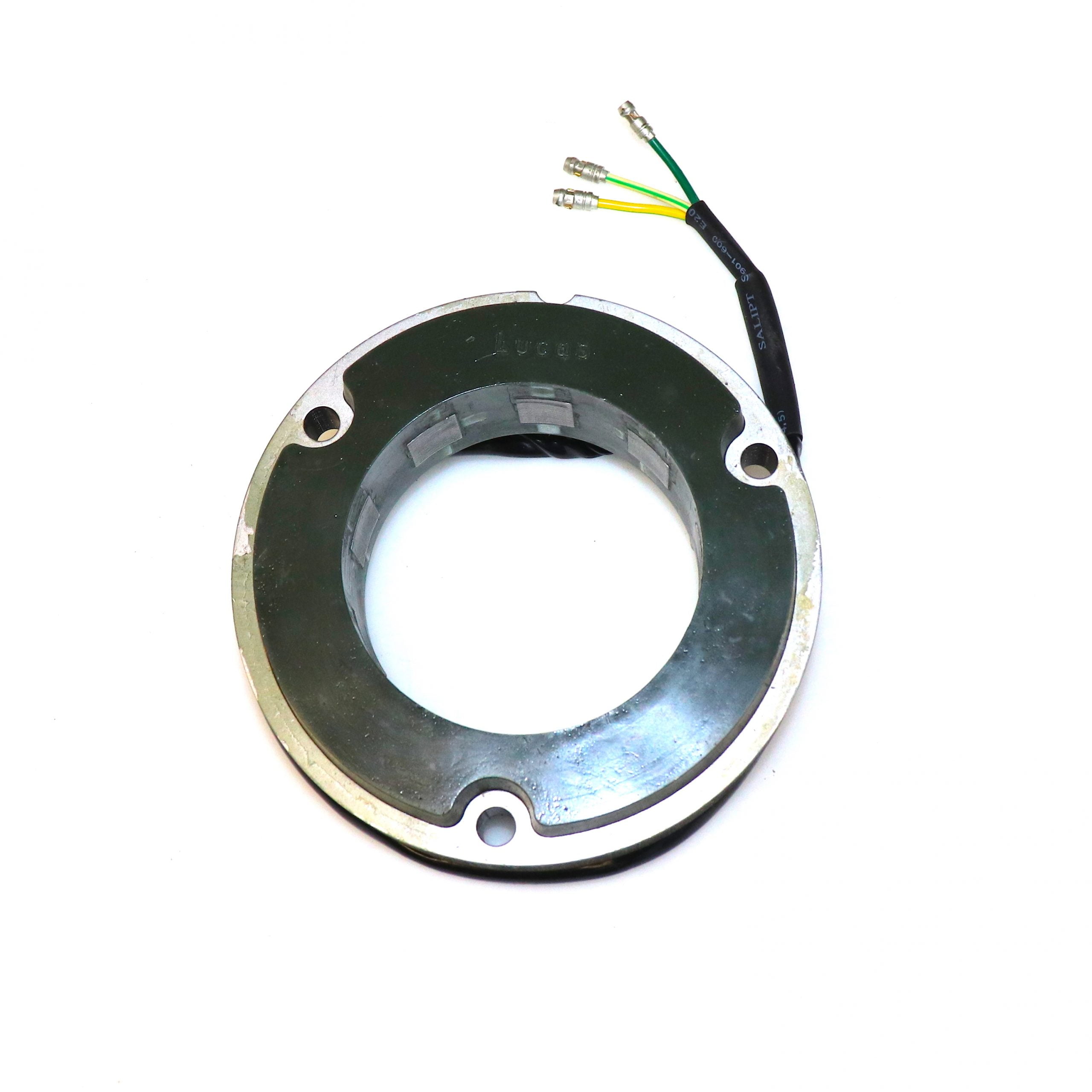
3 Phase Alternator
Thomas has fitted a 3 phase Lucas alternator – a great choice for superior charging in modern traffic conditions – typically you’ll see a positive charge at around 1,000rpm compared to the equivalent single phase alternator that will only swing to positive between 2,000 and 3,000rpm.
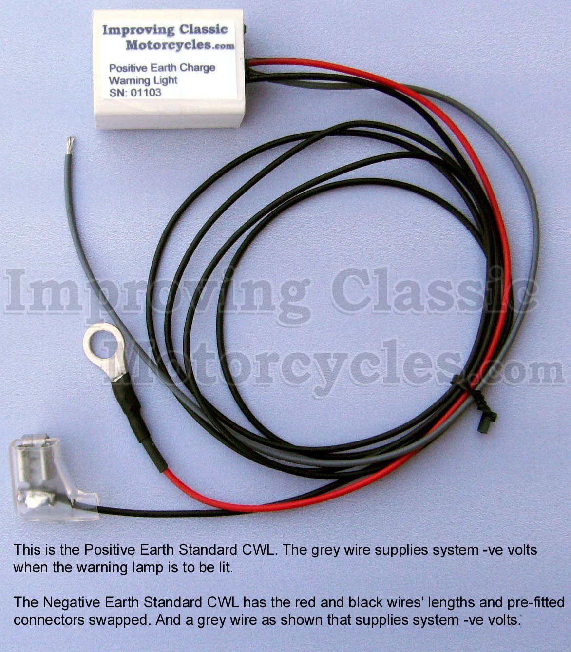
Charge Warning Light
A worthwhile upgrade that is worth it’s weight in gold is adding a Charge Warning Light in lieu of the standard warning light assimilator. This is another component whose wiring must be altered for a negative earth bike.

The nice thing about the Improving Classic Motorcycles unit is that you can retain the original warning light – so it looks totally factory.
It gives you a lot more useful information about the state of the battery and charging system compared to the standard assimilator unit, which looks for AC output from the alternator stator only.
Be Heard
Thomas has fitted twin horns on his bike – a great safety addition.
In order to lighten the load going through the handlebar switchgear, the twin horns operate via a relay and their own dedicated fuse back at the battery.
Tweaks
Thomas has removed the Power Socket, to tidy things up on the bike.
He has also removed the Lucas flasher unit in favour of an upgraded, solid state version. This has it’s own dedicated wire for the turn signal warning light, so Thomas has run a new NY (brown/yellow) cable up to the warning light in the headlamp bucket.
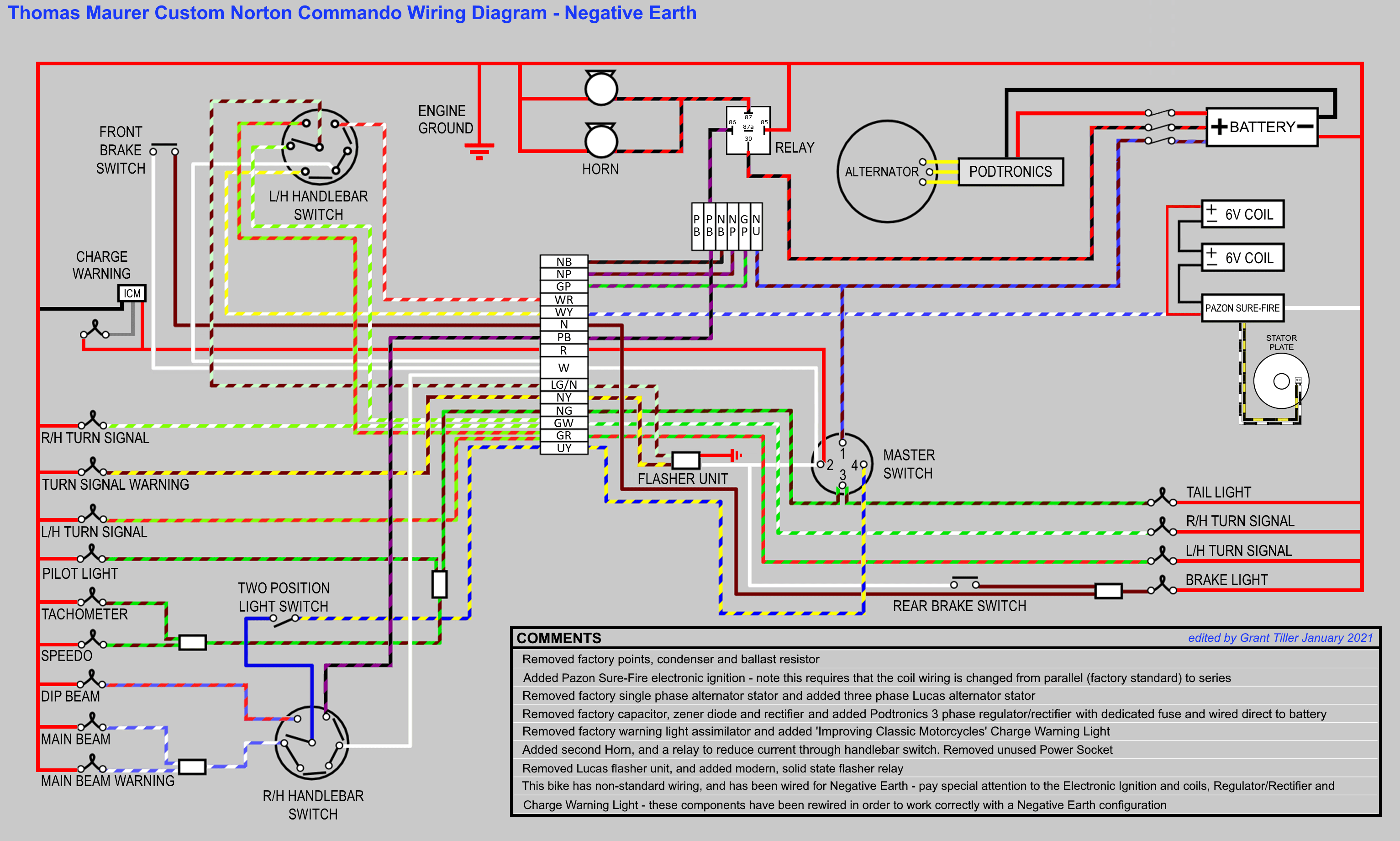
Wiring Diagram
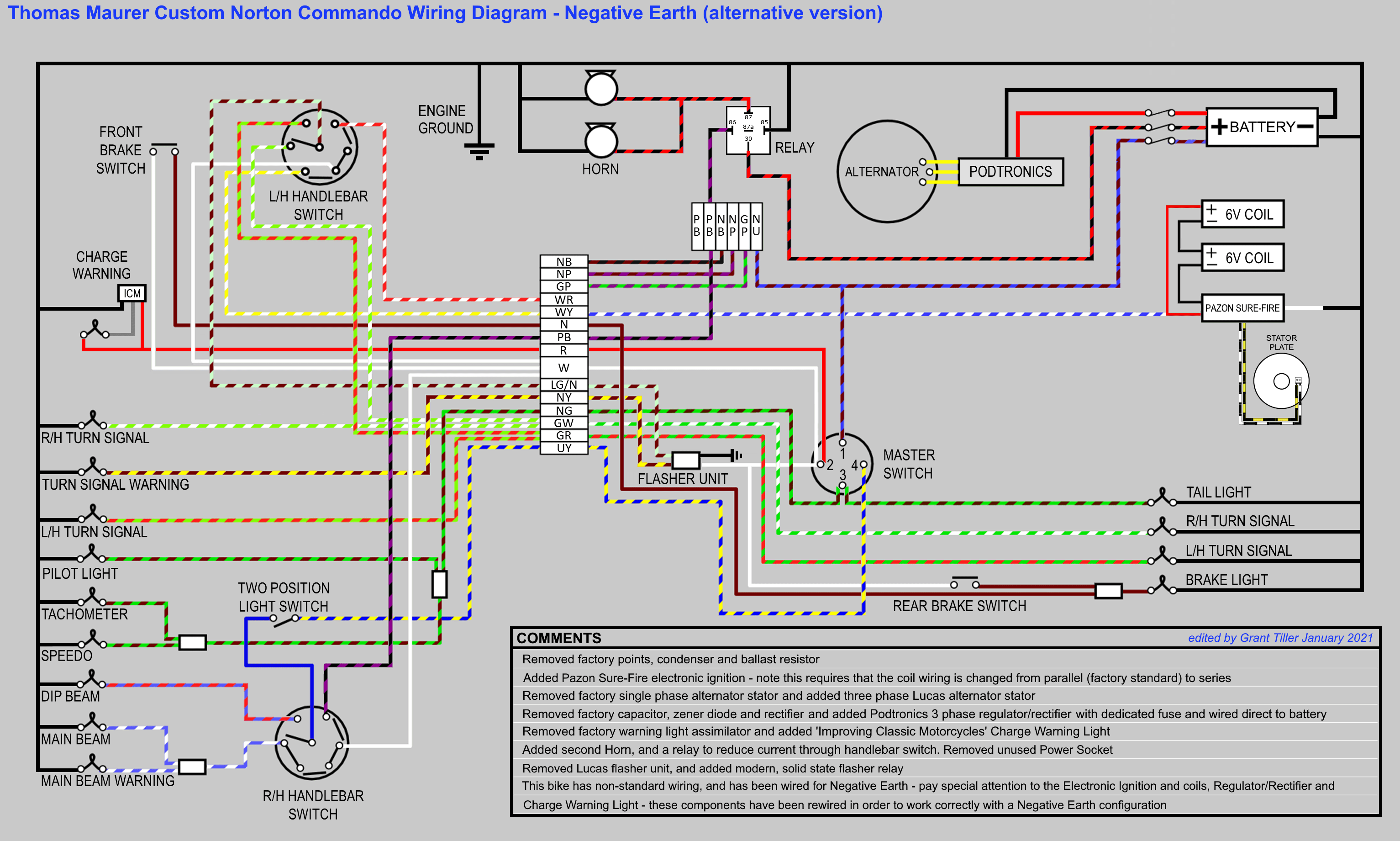
Here is the wiring diagram for Thomas’s negative earth bike.
Custom Norton Commando Wiring Diagram – Thomas Maurer PNG 3066×1841
This is available as a PDF too – it can be downloaded here.
But wait…
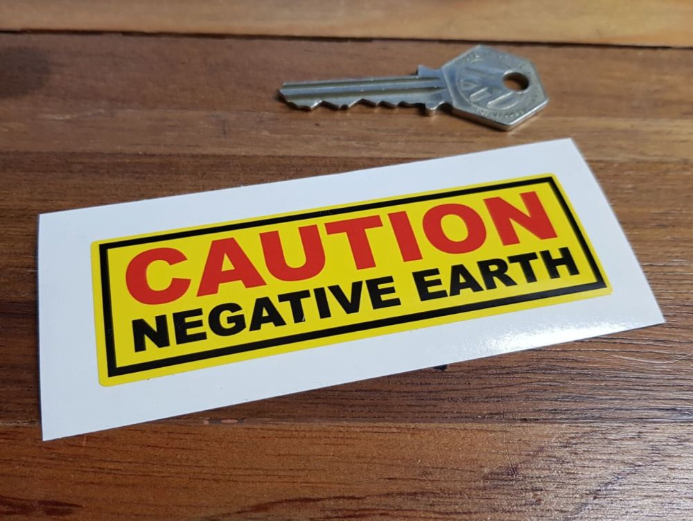
When you swap a bike to negative earth that was originally positive earth, all the factory standard red wires on the bike become the negative return to the battery.
This can become quite confusing – especially for other people that are not familiar with this actual bike.
One of the things I like to do is add a reminder under the seat and the tank – these stickers are available from places like ebay and are a great addition in my opinion.
The other thing I like to do is sleeve the red wires wherever possible with black heat shrink tubing, so that the red wire are permanently coloured black and match the world accepted standard of being negative.
So with that thought in mind, here is an alternative version of the same wiring diagram for Thomas’s bike – on this one, I have coloured the red wires in black to make it easier to understand.
Alternative Custom Norton Commando Wiring Diagram – Thomas Maurer PNG 3066×1841
This is available as a PDF too – it can be downloaded here.