Bill Hayley is in the process of restoring his 1972 Norton Commando. He bought it new in 1973 from Elite Motors.
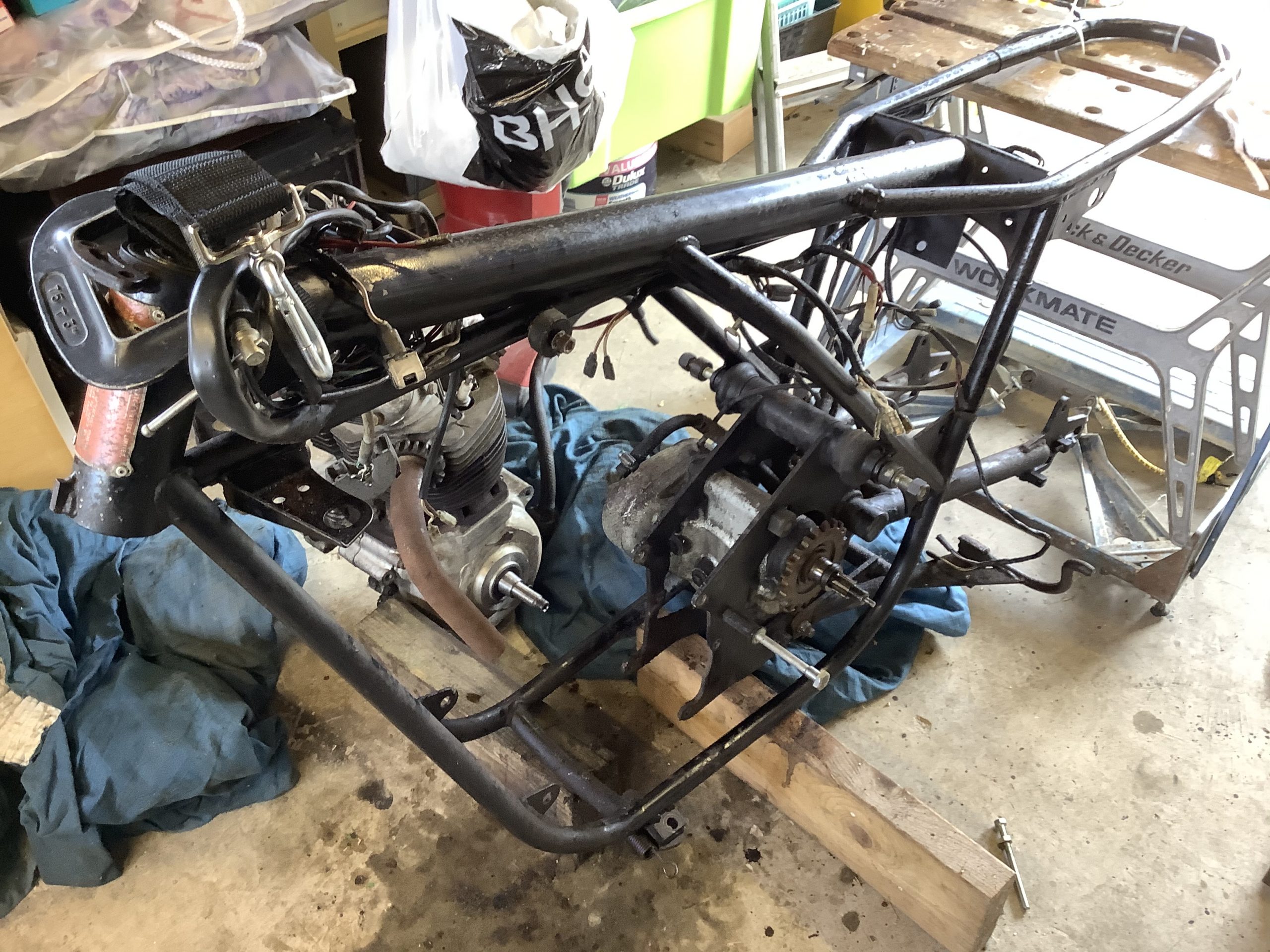
Bill is having the engine and gearbox professionally restored, his wheels are being rebuilt and he is had the frame powder coated.
Lots of parts are being rechromed, and it’s sounds like it is going to be better than new by the time Bill has finished!
He reached out initially via Facebook for recommendations on the wiring – he wants to simplify things, and make a few upgrades along the way.
Electronic Ignition

The new kid on the block for Electronic Ignitions is Tri-Spark.
Well, I say new kid – they have been around since about 2009.
You can find the Tri-Spark website here.

Tri-Spark get a bad press for reasons I have gone into in an article here – I have never, ever had an issue with them – always reliable, great customer service, and full of some great features.
They are my personal preference for electronic ignitions, and I recommend them to anyone thinking of moving based on my own great experience.
The Tri-Spark unit is a one box solution – all the gubbins are mounted inside the points cover – no additional black box to try and hide under the tank, and very, very simple to connect up.
The wiring is as follows:
- Red wire – this is the positive feed to the Tri-Spark unit. Most people attach this wire to one of the two fixing posts inside the points cover. I would personally recommend running an additional wire up to the coils and have drawn the wiring diagrams accordingly.
- Black/Yellow – this is the negative feed to the Tri-Spark unit. This joins in to the White/Blue wire that used to feed the Ballast Resistor that you are removing. As standard, this goes up to the big connector block under the tank, where it’s joined to the White/Yellow that is the kill switch on your left side handlebar switch cluster.
- Black/White – this is the negative supply FROM the Tri-Spark TO the coils.
As with the Boyer, from a wiring perspective, the most important thing to note is that you will be moving from a pair of coils that are wired in parallel to series.
Originally, the points make and break the positive (earth) side of each coil in turn.
The Tri-Spark electronic ignition system uses a concept called “wasted spark” – with the two coils wired in series, they are energized together on every rotation of the camshaft.
You’ll note in the wiring diagrams below that the Ballast Resistor and Condensers have been removed as part of the conversion to Electronic Ignition.
Two major benefits of the Tri-Spark:
- a very low operating voltage – as low as 8 volts means your bike will still run with a less than optimal battery and charging system
- circuitry performs the electronic equivalent of advance and retard to make the bike easier to start and stop the possibility of kick-back. This makes it gentler on your knees, and kinder to electric start systems (aka the delicate Commando sprag clutch)
Charging
This is always an interesting topic!
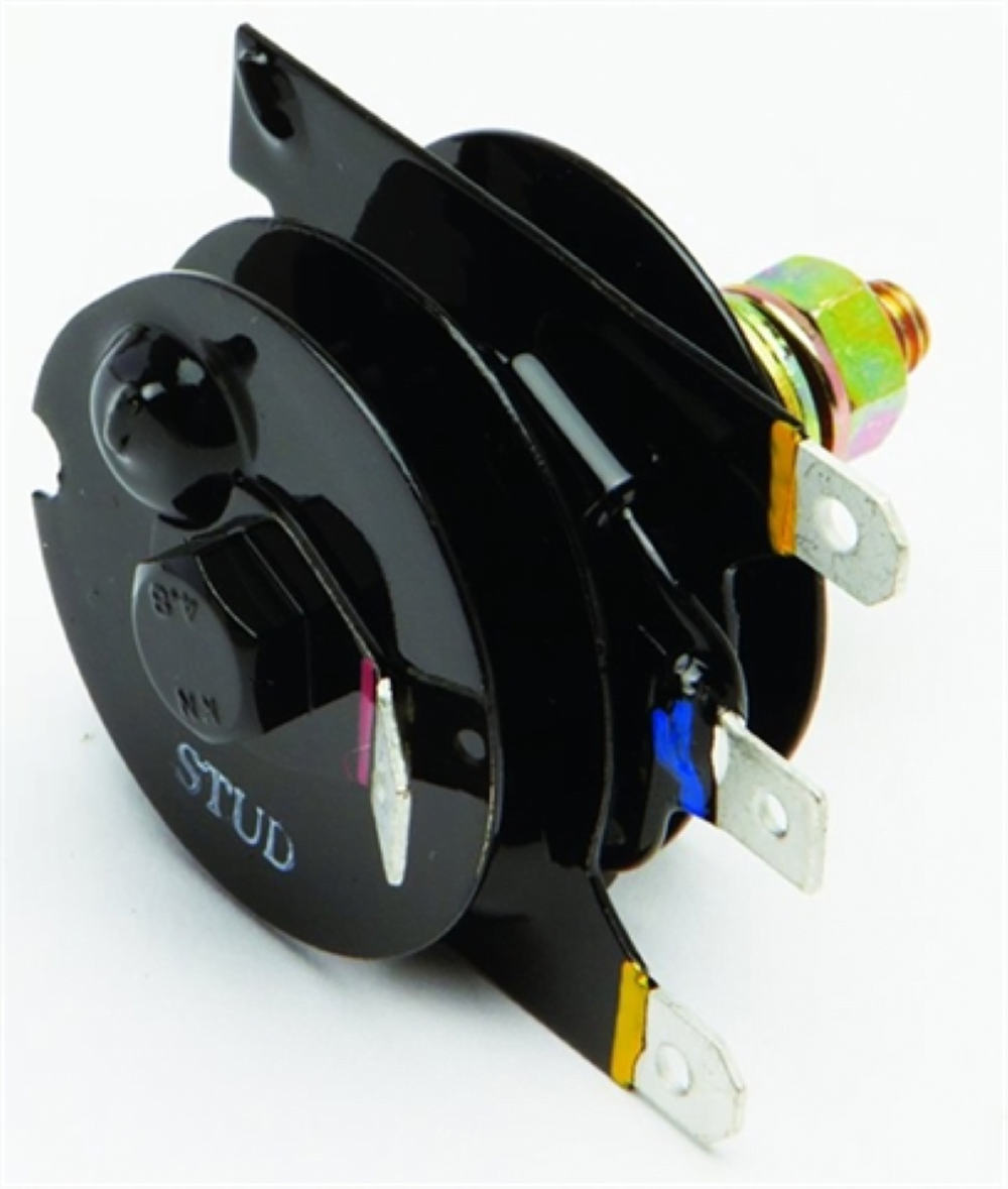
Bill has decided to keep his zener diode – which I think is a superb idea.
These things have been regulating voltage for the last 50 years on our bikes, and they do a great job!
They are attached to the z-plate whose aluminium mass acts as a pretty nice heatsink, plus they are stuck out in air flow, which is perfect for whipping away excess heat.
It is important that these are kept clean – one of the challenges with where it is situated means they are susceptible to picking up a bit of road dust and dirt. But that is easy to deal with.
Zener diode Lucas Part Number LU49345:

For rectification (converting the AC that the alternator stator makes, to DC that can charge the battery), Bill is upgrading the standard silicon full wave bridge rectifier.
Original fitted is Lucas Part Number LU49072 (2DS506) which can be really susceptible to vibration (diodes are soldered between the cooling fins, and these can rattle themselves apart):
So instead he will fit a modern rectifier (they are less than five dollars to buy) and do exactly the same as the original one, they are just packaged more robustly – they work perfectly!

Charge Warning Light
In lieu of there being no assimilator currently fitted, Bill has got a Charge Warning Light ready to go on the bike – he has got it from Improving Classic Motorcycles.

These units give you a lot more useful information about the state of the battery and charging system compared to the standard assimilator unit, which looks for AC output from the alternator stator only.
Bill has gone for the “Deluxe” version, which includes an LED that pushes into the standard Lucas bulb holder.

General Tidy Up
I have taken this opportunity to remove the superfluous Interpol wiring, as it is of course not required on this bike.
Bill has elected to remove his Power Socket too in order to help keep things neat and tidy.
Wiring Diagram
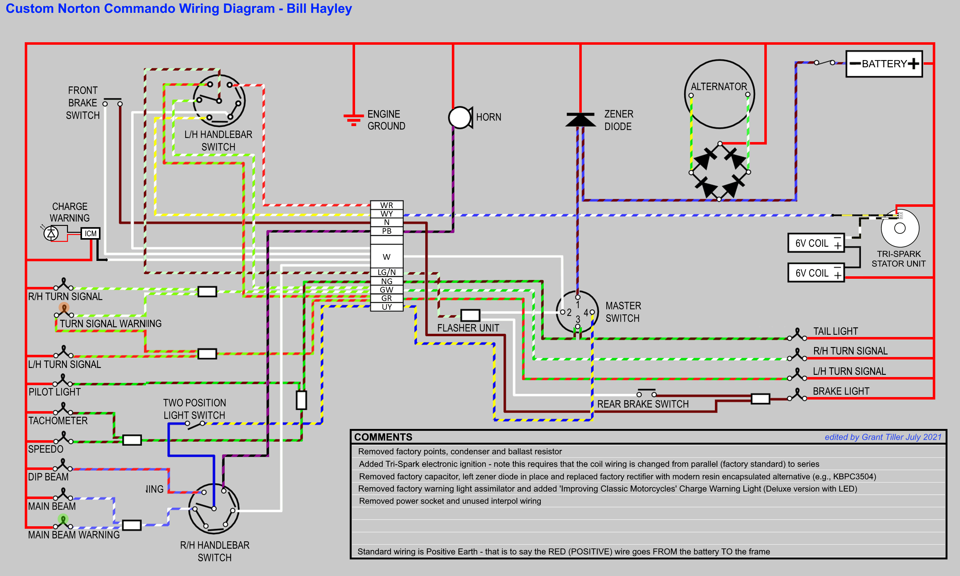
Here is the wiring diagram for Bill’s 1972 Commando.
Custom Norton Commando Wiring Diagram – Bill Hayley PNG 3066×1841