


Peter has made a few changes to his 1971 Norton Commando.
Electronic Ignition
A really popular Norton Commando upgrade is to move from the old points-based ignition system over to Electronic Ignition.
One of the most common units of the time is Boyer Bransden, who have been around since 1969.

They are still going today, and their website can be found here.
Moving from points to Boyer electronic ignition is a pretty simple upgrade.
From a wiring perspective, the most important thing to note is that you will be moving from a pair of coils that are wired in parallel to series.
Originally, the points make and break the positive (earth) side of each coil in turn.
The Boyer electronic ignition system uses a concept called “wasted spark” – with the two coils wired in series, they are energized together on every rotation of the camshaft.
You’ll note in the wiring diagrams below that the Ballast Resistor and Condensers have been removed as part of the conversion to Electronic Ignition.
The color coding of the wiring is simple:
- The Red – this is the positive feed to the Boyer, and is usually picked up from the red wire that goes to the Coil positive terminal.
- The Black – this is the negative supply FROM the Boyer TO the coils.
- The White – this is the negative feed to the Boyer. This joins in to the White/Blue wire that used to feed the Ballast Resistor that you are removing. As standard, this goes up to the big connector block under the tank, where it’s joined to the White/Yellow that is the kill switch on your left side handlebar switch cluster.
- Black/Yellow and Black/White – these go from the Boyer black box (they call it the Transistor Box) down to the Stator Plate that sits behind the points cover.
Regulator/Rectifier
Another of the most common upgrades or modifications for a classic british bike is to add a combined regulator/rectifier unit.
Our Commandos use a blue can capacitor, zener diode (which can be found mounted on the back of the z-plate) and rectifier unit.
A combined regulator/rectifier replaces all of these components with one package.
Peter has gone for the new to market Tri-Spark MOSFET unit.
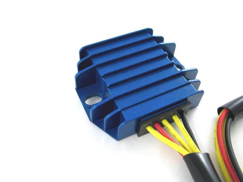
It is certainly easy to spot in it’s blue anodised heat sink!
There are four wires to connect:
- Two Yellows – these are the AC input and pick up on the Green/Yellow and Green/White (connection can be any way round, as this is the AC side of the circuit)
- The Red – this is the Positive output and will join to the red wire if you are using existing wiring (it goes straight to the ground/earth of the frame)
- The Black – this is the Negative output (known as the hot wire) – it will pick up on the Brown/Blue wire (which goes via a fuse straight to the battery negative terminal)
The spec on paper is very good, being able to handle up to 20 amps.
And the benefit of MOSFET is much more precise control of the charge voltage.
Here are the wiring instructions for the Tri-Spark VR-0030 MOSFET regulator/rectifier.

The other piece of great news is that our friends over at Andover Norton are carrying this unit in their inventory!
Their part number is 13.1801 and you can find it here:

Here is a picture of Peter’s lovely bike:

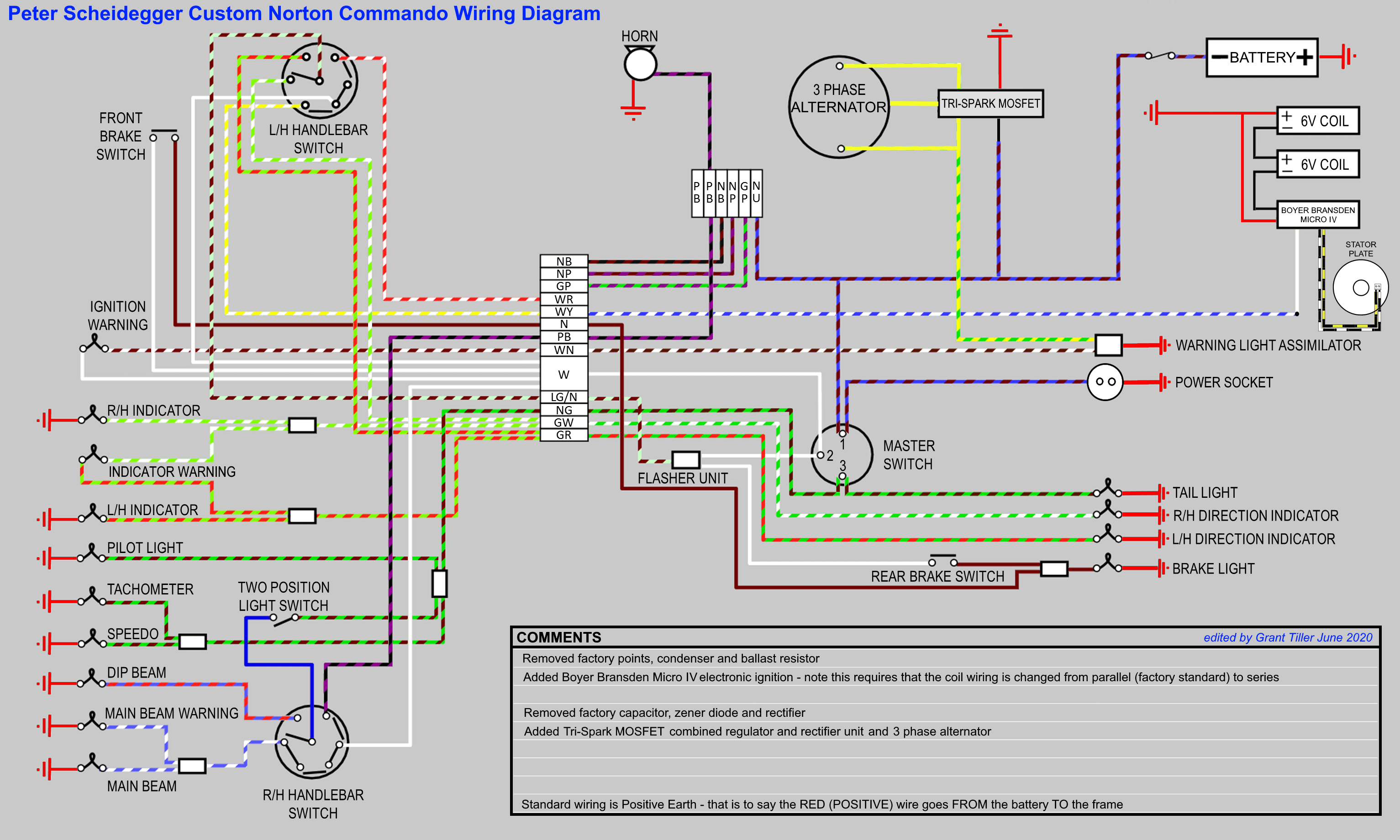
Wiring Diagram
Here is the wiring diagram with the Tri-Spark MOSFET regulator/rectifier added together with the three phase alternator:
Custom Norton Commando Wiring Diagram – Peter Scheidegger PNG 3066×1841
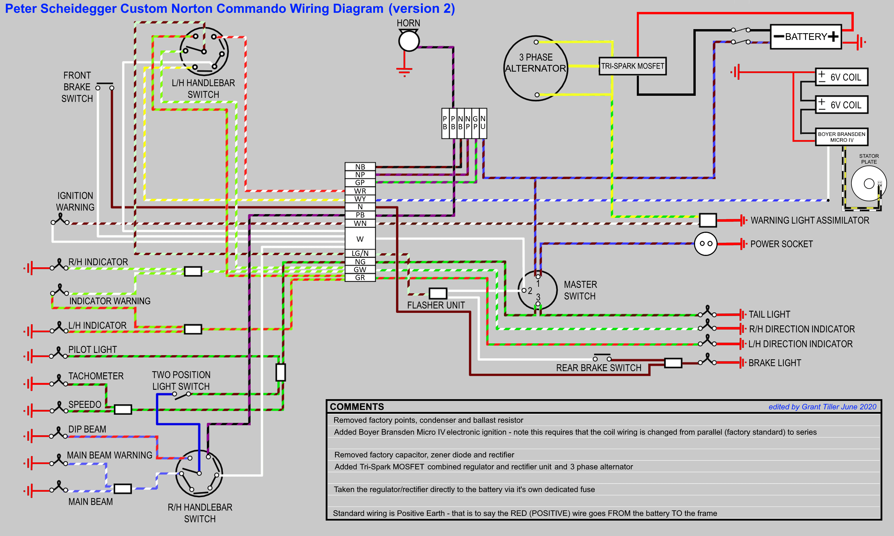
But wait…
An alternative way to wire in the regulator/rectifier is with it’s own dedicated fuse.
This is a popular option for people that have had charging issues in the past, as it provides additional piece of mind.
If your regulator/rectifier fails, it could blow it’s own fuse, leaving you with enough power in your battery to get you safely back home again.
Alternative Custom Norton Commando Wiring Diagram – Peter Scheidegger PNG 3066×1841
Warning Light Assimilators
It is important to note that MOST aftermarket reg/rec manufacturers do not support either the pre-MK3 Lucas 3AW silver can warning light assimilator OR the MK3 one.
Boyer Bransden are very explicit in their instructions for the Power Bow – they have even made an alternative Power Box model that includes a charge warning light.
Other manufacturers (PODtronics, SPARX and the Tri-Spark MOSFET units) either mention it in their smallprint/FAQs or neglect to mention it at all.
As such, I would recommend NOT using the original assimilator and consider your alternatives.
You could replace your assimilator with a solid state equivalent like the CoolCat Express (warning: you have to buy positive SS3AW-P or negative SS3AW earth)
Alternatively, you could follow my recommendation and buy a Charge Warning Light instead.
A warning light assimilator tells you that the alternator stator is producing an AC output, whereas a Charge Warning Light tells you that the battery is charging, the reg/rec is working and it gives you much more useful information about performance of the charging system and the state of charge.
I personally recommend the Improving Classic Motorcycles “Standard” Charge Warning Light. This model wires in to the standard incandescent lamp, so it looks better than a modern LED. It matches all your other warning lamps, which is particularly important on the MK3 with it’s instrument ‘console’
The ‘brainbox’ is about the size of a postage stamp, and can easily live inside the headlight bucket or under the MK3 ‘console’
Hi Grant,
you are the guy who makes me a little bit more optimistic… I try now for weeks (?) to get a new wiring on my commando (750, built 73). There are some changes I want to do: neg. earth circuit, Lucas Three Phase Alternator, Boyer-Bransden ignition system (Micro MK IV), Podtronics-Power-Module, charge warning light kit (Graham Blighe, http://www.improvingclassicmotorcycles.com), and a fuse-box with 3 (4?) additional fuses. And what should I say…
It seems I need some help. In the German britbike-Forum I found a hint to your (great!) homepage. I hope you find some time to help me with a wiring diagram with all my „specialties“. Yes, I know there are a lot of wiring diagrams for the Commando, but I‘m still confused… (sorry for my english)
Klaus (from Germany)
Hi Klaus,
Your English is fine – way better than my German!!!
I would be happy to create a custom wiring diagram for your bike.
Are you SURE that you want negative earth though?
My usual recommendation is to keep it factory.
It means that people like me can look at the factory wiring diagrams and actually be of some help to you if you have a problem.
Also, I have seen on many occasions boiled batteries and melted wires when someone helpful on the roadside has gone in to lend a hand and inadvertently caused untold damage.
When swapping to negative earth, from the factory positive, every red wire on your bike becomes a negative wire – which is confusing.
Plus every book, article, manual and drawing becomes wrong for your bike.
Most people think they want negative earth so that they can run LED lights and USB chargers.
However, your charger can still work fine and you can easily get LEDs that run on positive earth bikes.
Of course it’s your choice – I will make you a negative earth drawing if that’s what you want, but it would be something I strongly advise you against.
Let me know,
Grant.
Hi Grant,
Thank you for your answer. Yes, let‘s say “I spent some sleepless nights“ to decide original or not. And I would like to have negative earth. And know I appreciate your advice!
Thank you!
Klaus
No problem Klaus – I just wanted you to be 100% aware!
Here is the link to your wiring diagram:
https://granttiller.com/custom-norton-commando-wiring-diagram-klaus-volmle
Hopefully this is what you are looking for, and it puts an end to your sleepless nights!
Cheers,
Grant