Peter Taylor reached out to me here at the site for a steer on some electrical upgrades he is doing to his bike. Of course I am only too happy to help where I can.
This machine is receiving a real slew of updates, which will bring it into this century, and help make it much more suitable for riding in today’s modern traffic conditions.
Peter has kept it classy, and gone to my good friend Matt Rambow at Colorado Norton Works for many of his upgrades.
Electric Starter

Matt Rambow and his team at Colorado Norton Works make some beautiful stuff, and their Electric Start Conversion for the pre-MK3 Norton Commando is no exception.
The cNw kit, found here is actually very reasonably priced at $2,795 if you consider that it includes a belt drive primary.
The pics are from Matt’s site (not Peter’s bike)

As always with Colorado Norton Works, the quality of the fit and finish is second to none.
If you don’t want a highly polished finish, there are options for satin and matt black too.

Matt supplies a starter button with his kit, as the quality of the original switches were dubious when they were new. That makes it difficult for Matt to support, and guarantee the reliability, hence shipping his own.
Peter has also replaced the left handlebar switch too, which I will cover further on.
Electronic Ignition

Peter is using the Tri-Spark electronic ignition – they have been around since about 2009.
You can find the Tri-Spark website here.

Tri-Spark get a bad press for reasons I have gone into in an article here – personally I have never, ever had an issue with them – always reliable, great customer service, and full of some great features.
They are my personal preference for electronic ignitions, and I recommend them to anyone thinking of moving based on my own great experience.
The Tri-Spark unit is a one box solution – all the gubbins are mounted inside the points cover – no additional black box to try and hide under the tank, and very, very simple to connect up.
The wiring is as follows:
| Wire Colour | Description |
|---|---|
| Red | this is the positive feed to the Tri-Spark unit. Most people attach this wire to one of the two fixing posts inside the points cover. I would personally recommend running an additional wire up to the coils, I always draw my wiring diagrams in this way to cover this recommendation |
| Black/Yellow | this is the negative feed to the Tri-Spark unit. This joins in to the White/Blue wire that used to feed the Ballast Resistor that you are removing. As standard, this goes up to the big connector block under the tank, where it’s joined to the White/Yellow that is the kill switch on your left side handlebar switch cluster |
| Black | this is the negative supply FROM the Tri-Spark TO the coils |
As with most electronic ignitions, from a wiring perspective, the most important thing to note is that you will be moving from a pair of coils that are wired in parallel to series.
Originally, the points make and break the positive (earth) side of each coil in turn.
The Tri-Spark electronic ignition system uses a concept called “wasted spark” – with the two coils wired in series, they are energized together on every rotation of the camshaft.
You’ll note in the wiring diagram below that the Ballast Resistor and Condensers have been removed as part of the conversion to Electronic Ignition.
Two major benefits of the Tri-Spark:
- a very low operating voltage – as low as 8 volts means your bike will still run with a less than optimal battery and charging system
- circuitry performs the electronic equivalent of advance and retard to make the bike easier to start and stop the possibility of kick-back. This makes it gentler on your knees, and kinder to electric start systems.
Regulator/Rectifier
Another of the most common upgrades or modifications for a classic british bike is to add a combined regulator/rectifier unit.
Our Commandos use a zener diode (which can be found mounted on the back of the z-plate) and rectifier unit.
A combined regulator/rectifier replaces all of these components with one package.
Peter has gone for the relatively new to market Tri-Spark MOSFET unit.
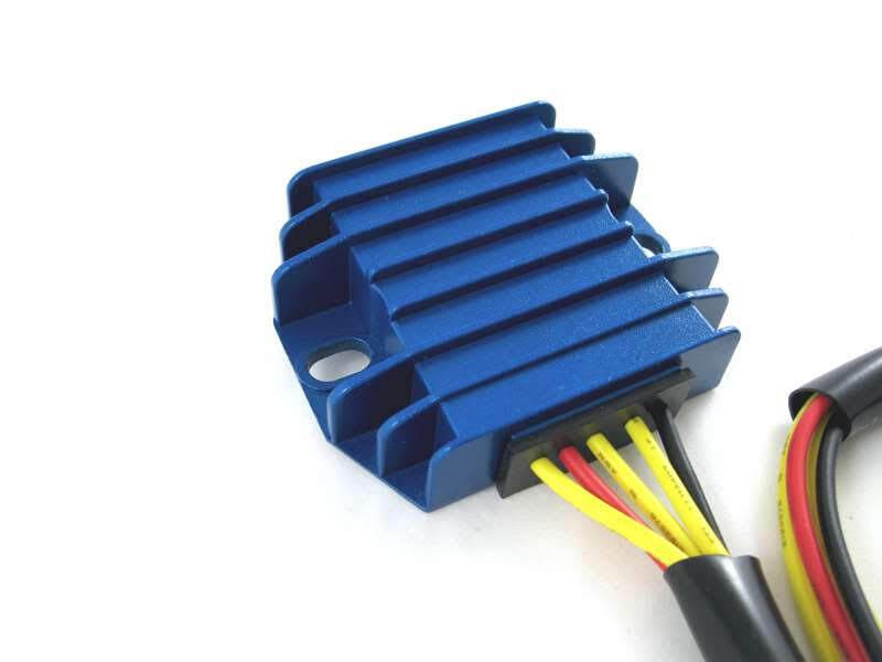
It is certainly easy to spot in it’s blue anodised heatsink!
There are five wires to connect:
| Wire Colour | Description |
|---|---|
| Yellow (x 3) | these are the AC input and pick up on the three wires coming out of the three phase alternator stator (connection can be any way round, as this is the AC side of the circuit) |
| Red | this is the Positive output and will join to one of the red wires in the harness |
| Black | this is the Negative output (known as the hot wire) – it will be wired to the NU (brown/blue) that goes back to the battery negative terminal via a fuse |
The spec on paper is very good, being able to handle up to 20 amps.
And the benefit of MOSFET is much more precise control of the charge voltage. I have done a deep dive into reg/rec types and behaviour which you can find here
Here are the wiring instructions for the Tri-Spark VR-0030 MOSFET regulator/rectifier.

The Tri-Spark MOSFET reg/rec is available at many stockists including from our good friends over at Andover Norton who are carrying decent stock levels of this unit in their inventory!
Their part number is 13.1801 and you can find it here:

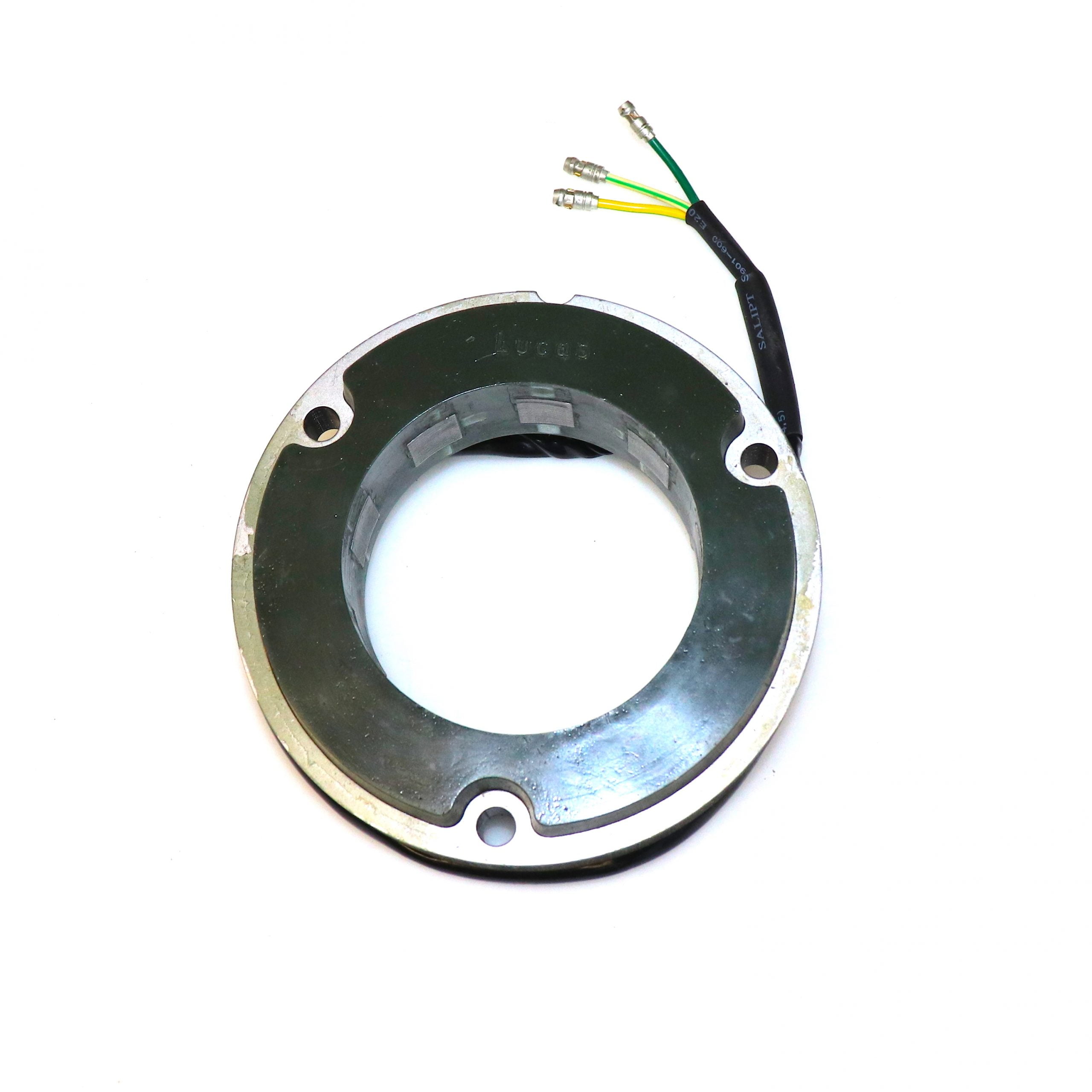
Alternator Stator
Peter has fitted an RM24 3 phase Lucas alternator – this is a nice choice for superior charging in modern traffic conditions, especially when you have an electric starter.
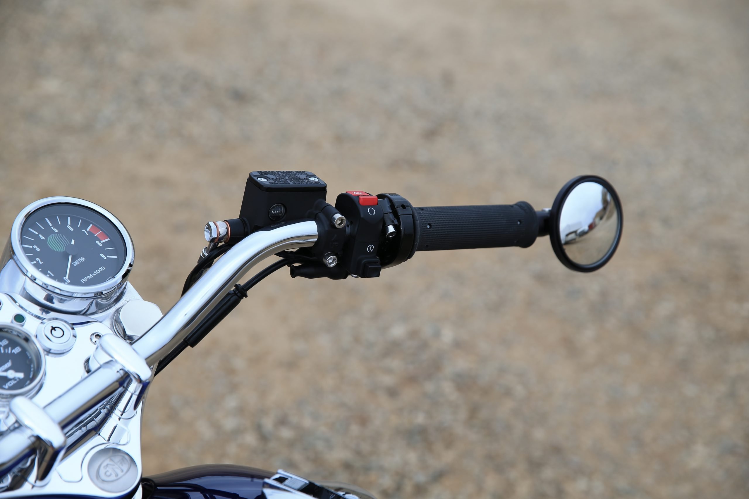
Handlebar Switchgear
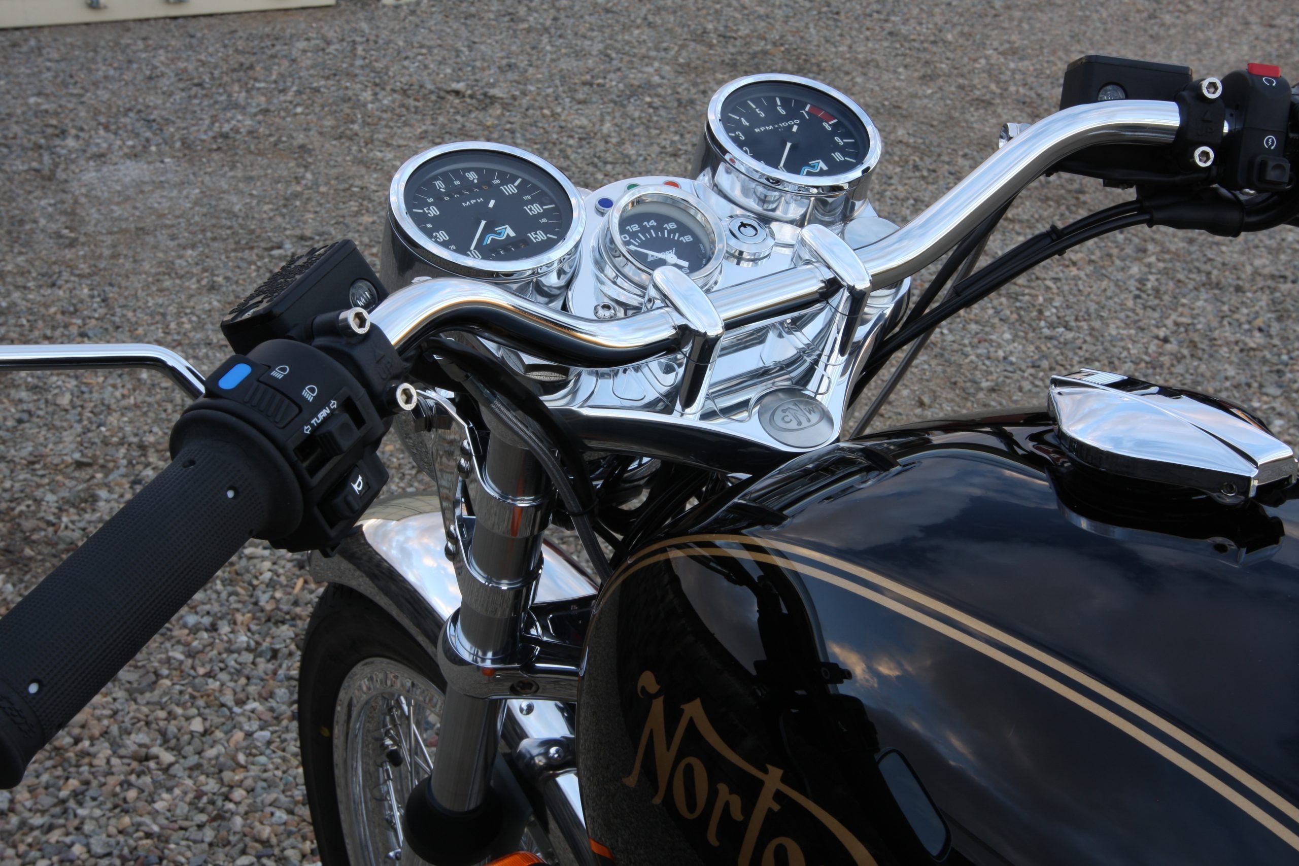
Peter has replaced both left and right handlebar switches with the modified Honda units from Coloardo Norton Works.
It makes for a bit of a weird colour splice of cables, but I have indicated what goes where in the wiring diagram.
It’s well worth doing, as the quality is superb, and if you are replacing the original levers with upgraded alternatives, it is a no brainer.
It leaves only the starter button and engine stop switch on the right side, much preferred in my opinion.
Oil Pressure/Charge Warning Light
A worthwhile upgrade that is worth it’s weight in gold is adding a Charge Warning Light in lieu of the standard warning light assimilator.
In fact, the Tri-Spark MOSFET reg/rec does not support the standard assimilator anyway!

The nice thing about the ‘standard’ Improving Classic Motorcycles unit is that you can retain the original warning light – so it looks totally factory.
They also sell a ‘deluxe’ version which includes and LED
These units give you a lot more useful information about the state of the battery and charging system compared to the standard assimilator unit, which looks for AC output from the alternator stator only.
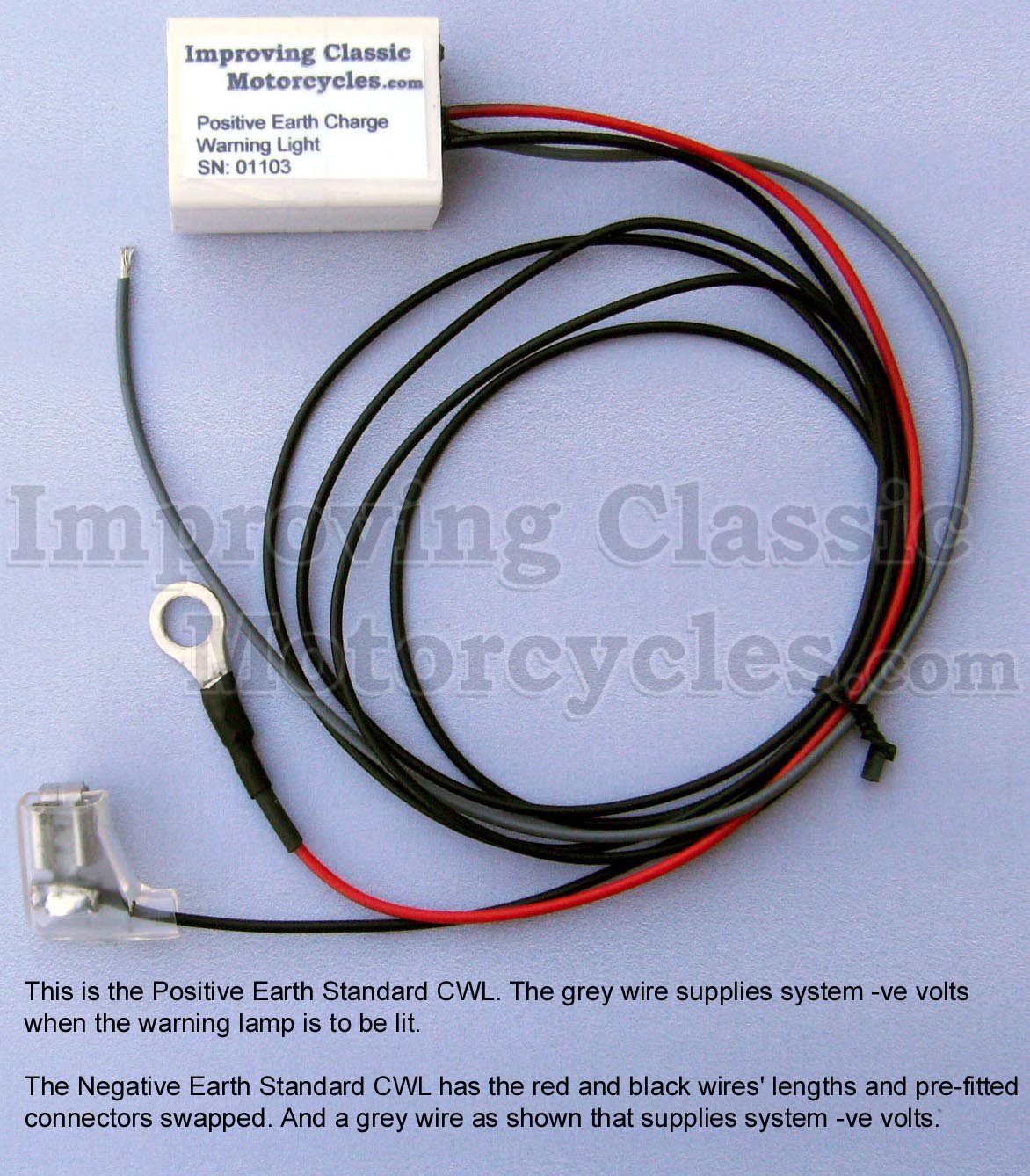
Peter has, in addition gone one stage further, and got the version which includes and extra wire for an oil pressure switch.
I think this is a superb idea, again giving you peace of mind that the oil pump is working.
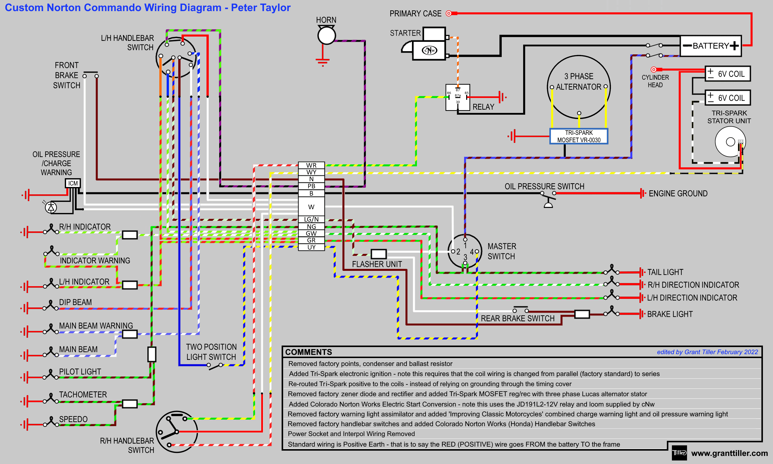
Wiring Diagram
Here is the Custom Wiring Diagram for Peter’s Commando.
Custom Norton Commando Wiring Diagram – Peter Taylor PNG 3066×1841
This is available as a PDF too – it can be downloaded here.