

I like to do my own wiring where I can, not because I feel the standard wiring on our bikes is poor – far from it, I think it is well thought out, and pretty reliable but because I make changes and upgrades and it gets to the point when sometimes it is quicker, easier, and neater just to start again.
This is not as daunting as it sounds, and I would encourage everyone to have a go. I wire to a diagram, and wherever possible try to keep the routing as factory standard as possible – that way it is easier for fault diagnosis in the future, plus it means that the documentation and the manuals are still applicable.
Indeed, wherever possible, I will always recommend sticking with positive earth, and keeping to the standard color codes for wiring.
I have read about, and fixed many issues that were made worse by ‘helpers’ at the side of the road, or even roadside recovery services that, through no fault of their own just made matters worse.
Ring
In my previous article Bad Earth I talked about how Norton and Lucas dealt with the positive feed, and how they didn’t rely on the frame as the positive feed from the battery – this was good thinking, and innovative for the time, however I do feel that this idea can be tweaked a little.
In the standard wiring harness, you’ll see that quite often a component will have two red positive wires attached to it.
In simplified terms, it looks like this:
Think of the standard setup like your home electric ring main – the first wire feeds the component, then the second wire leaves it and goes on to feed the next one down the line. It is sometimes referred to as daisy-chaining.
There are a couple of issues with this methodology:
If a wire is broken at any point, it can break the chain and interrupt the feed to the components further down the line.
Breaking this connection is quite likely given the fact they are terminated with male bullet terminals, and are pushed into female bullet connectors – the multi-way versions of these can become very brittle and unreliable as the rubber housing perishes and breaks down.
Having more than one connector at the component itself can put stress and strain on it – don’t forget, this is considered a harsh environment with high vibration, high temperature and sometimes grease and oil.
Bus
If I am making my own harness, or part of a harness, my preference is to make a BUS, and tap in to it where I need a positive feed.
Again, simplistically, it looks like this:

And for an electric start bike, it would look like this:
The advantage of a positive bus like this is that the branch connections (which I twist, solder and heatshrink) are made along the cable that runs from front to back of the bike.
This is taped, like the rest of the harness, so the connections are hidden, strained relieved, and protected from moisture and dirt ingress.
Not having two connectors at each component takes a lot of bulkiness away from the component itself, making it look a lot neater and tidier.
And, if for whatever reason one of the cables that feed a component got broken, cut, or the connector failed, it would not impact the positive supply through the rest of the bike.
Wiring Technique
When I am making up looms and harness from scratch, I like to minimize the number of connectors I use – ideally using them only at the point the cables plug in to the components themselves.
This feels contrary to what they did back in the 60s on bikes, where you seem to run into connectors for the sake of it – these are potential points for moisture ingress, terminal corrosion (the dreaded verdigris) and ultimately failure.
If I am splicing like in the case of the positive ‘BUS’ (covered above) that I like to run from front to back of a bike, I like to bare the cable using wire strippers where I want my splice to be, I then twist the junction wire around the bared section, solder it, and use an adhesive lined heatshrink sleeve over the top which will protect the joint from moisture ingress and provide decent strain relief.
I feel that mechanically twisting the cables as I do, and then strain relieving them so well means there is zero risk of a soldered joint becoming dry or failing – I have certainly never had a failure in many years.
Here are some pics of my splicing procedure:


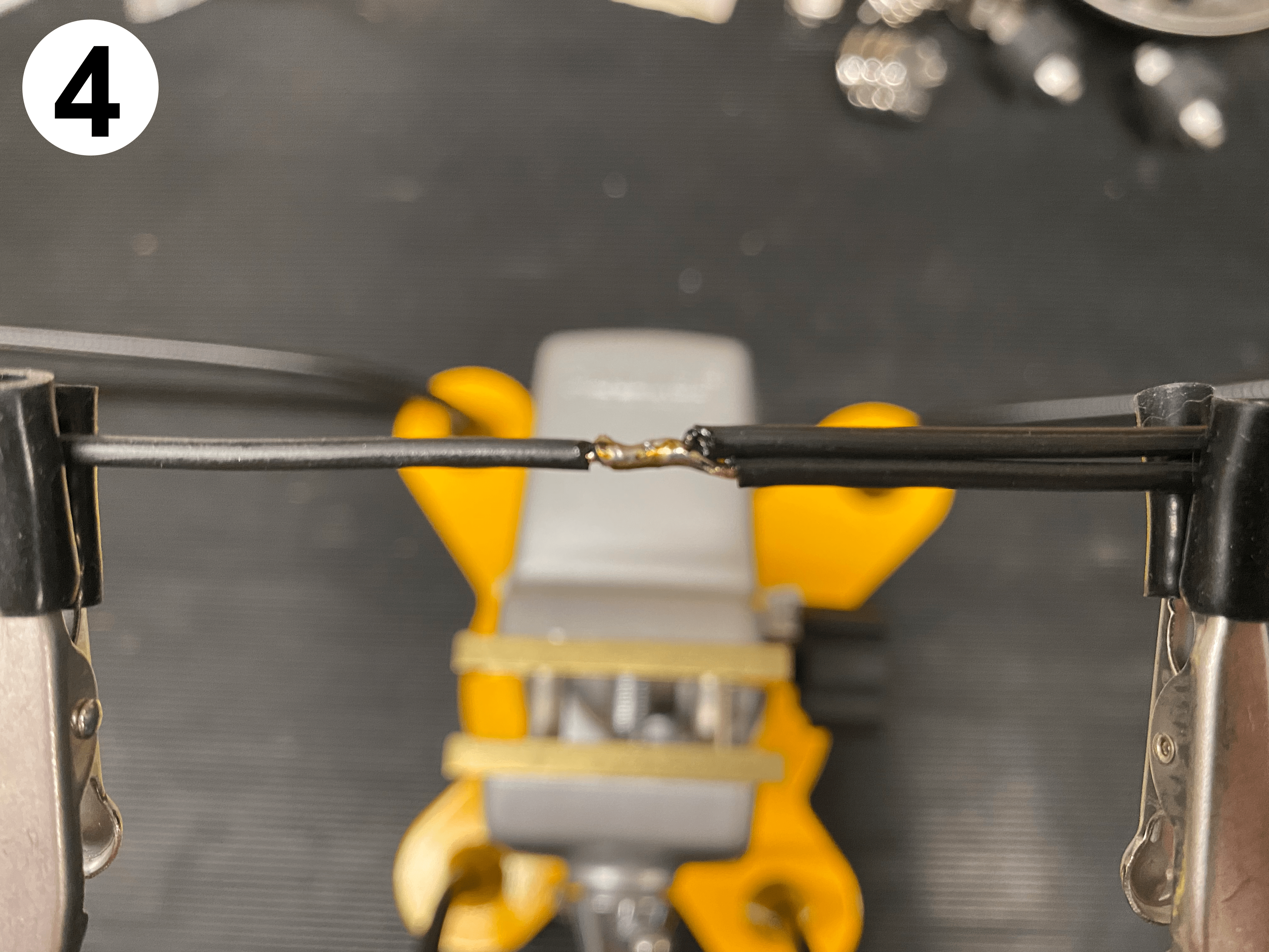
- Mark the wire where you want your tap to be
- Bare the wire using a craft knife, or automatic wire strippers
- Tightly twist your new branch wire onto the bared section
- Touch the soldering iron on to the joint, not too much solder, as you don’t want to make the whole section stiff and brittle
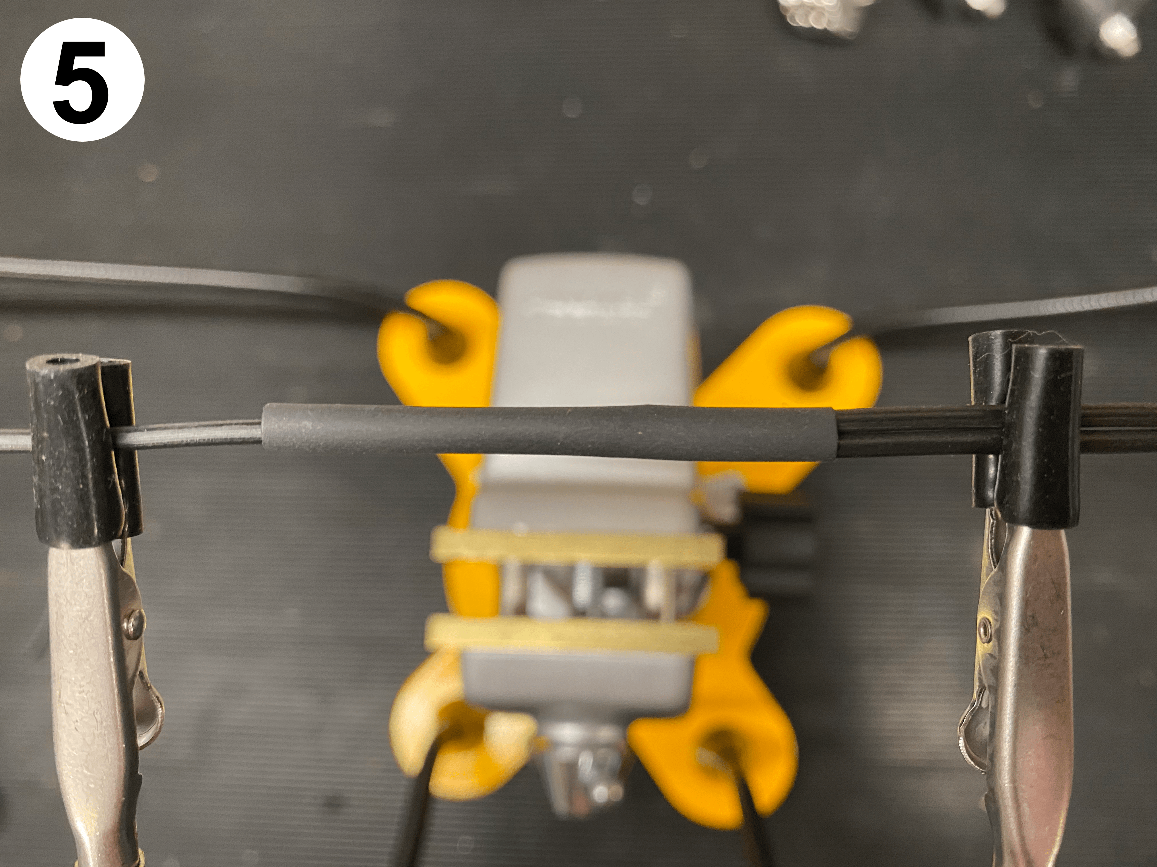
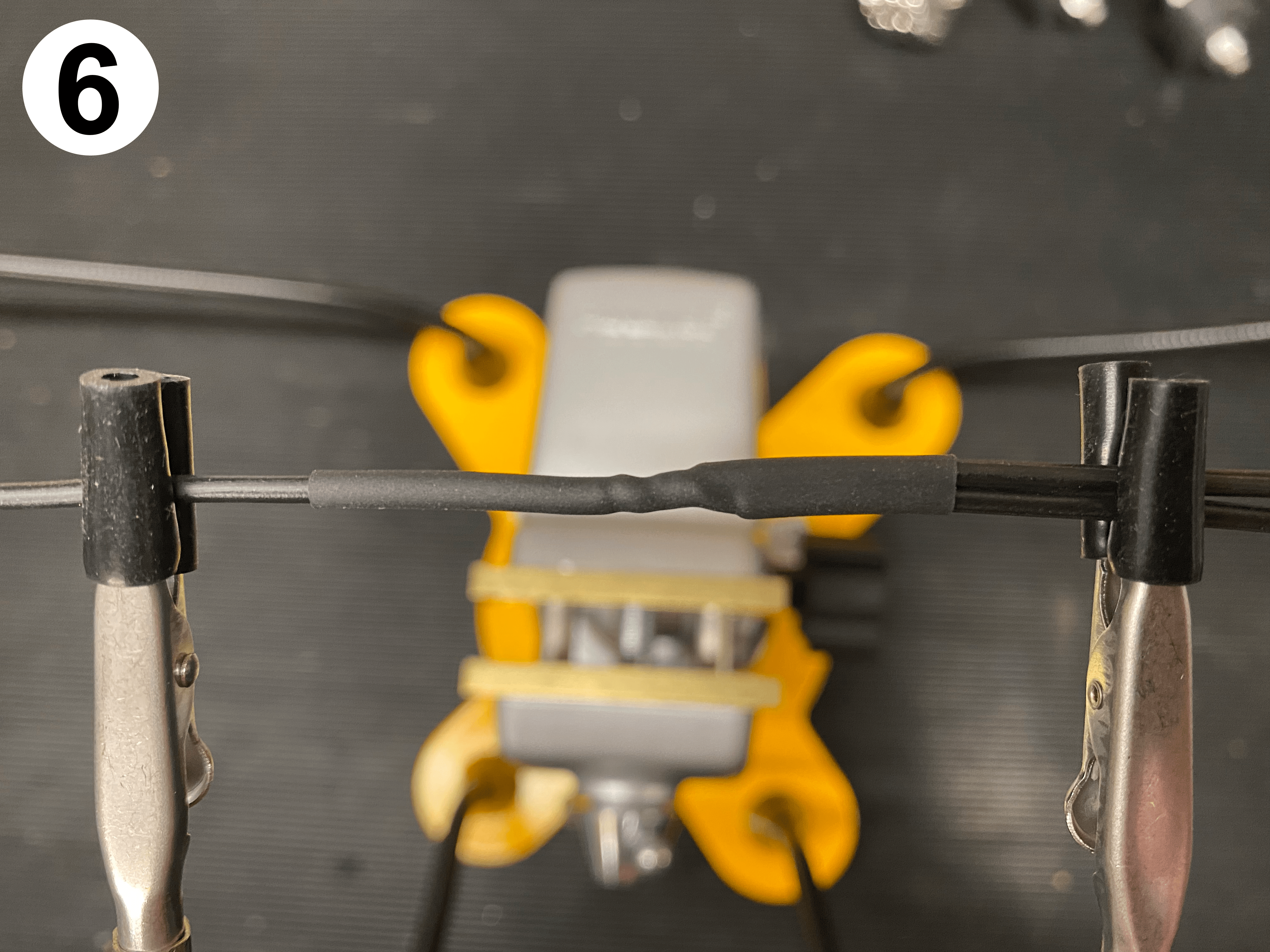
- Trim some heatshrink tubing (preferably adhesive lined) and thread it on
- Shrink the tubing in to place using a heat gun
I use a 24 volt soldering iron with a wide tip which I run at 450 degrees.
Hold the soldering iron under the twisted wire joint, then feed a little solder in to the top of the joint – nice and fast, and only the tiniest amount of solder needed.
I avoid soldering the connectors at the component end, much preferring crimp connectors. Using the correct crimping tool gives a good, solid, and robust connection that will not fail, and will withstand vibration.
When I have finished making the harness, and I wrap the whole thing in cloth tape, you’d never know there is a joint there!
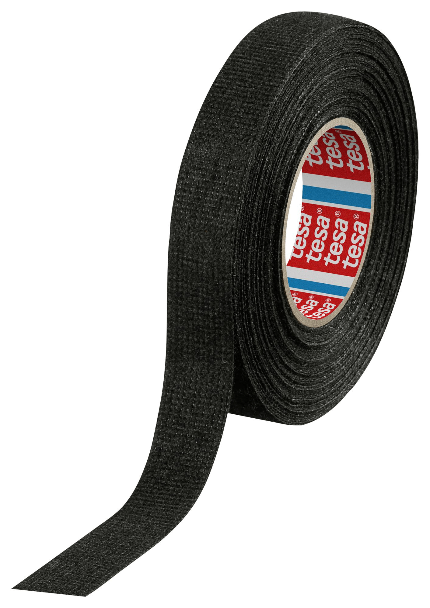
The tape I like to use is Tessa 51608 fabric tape (it is also known as fleece tape)
It’s nice and furry, sticks well to itself and doesn’t come unraveled. It gives a great OEM look.
Wire Sizing
it’s changed a bit, as Lucas used to have their own gauge wire made for them.
The typical wire sizes used by Lucas that we see on our classic bikes, are rated as follows:
- 44 strand
44/0.12 (44/0.30mm) 22 amp - 28 strand
28/0.12 (28/0.30mm) 14 amp - 14 strand
14/0.10 (14/0.25mm) 6 amp
14/0.12 (14/0.30mm) 7 amp - 9 strand
9/0.12 (9/0.30mm) 4 amp
Note 1 – the 14/0.10 was superseded by the 60s
Note 2 – modern cables of the same spec are rated higher than the figures Lucas give (as shown here)
The two companies that I use for my wiring are:
The wire types I use on bikes are mainly:
Thin Wall Cable
- 32/0.20, 1.0mm², 16.5A – cable OD 2.0mm
- 28/0.30, 2.0mm², 25.0A – cable OD 2.7mm
Which are available in the colour ways that match our bikes harness
32 is the number of strands
0.20 is the diameter in mm of each strand
1.0mm² is the cross sectional area of the copper
16.5A is the nominal current rating of the cable
cable OD 2.0mm is the outside diameter of the cable (so the total diameter including the cable jacket)
For the wire that runs from front to back of the bike (the backbone) use a cable that is rated higher than your fuse value.
This wire will need the current capacity to handle everything it feeds.
I usually select a 12 or 14 gauge cable for this:
Thin Wall Cable
- 44/0.30, 3.0mm², 33.0A, – cable OD 3.3mm
Hopefully this little trick helps someone who feels unsure about wiring – I have done several harnesses like this, and it works well.
Greg Marsh from the Access Norton forum also have a very similar technique – check out a wiring diagram he uses here: Greg Marsh Enterprises – Custom Wiring Diagram
Don’t be afraid, and know that you can always reach out to me if you need any advice.
Grant I’m in the process of ‘attaching’ a new loom to my 1971 Commando Fastback re-build. In the past I have successfully rebuilt Triumph and BSA triples and a Mk3 Commando. On each of these I have fitted a regulator and electronic ignition, then ‘unpicked’ the new loom to remove any wires that are not now needed with the removal of the ballast resistor, points, rectifier and zebor diode. I feel it safer than to have a mass of cables folded back on each other and then taped. In the case of the triples it was the black/red and black/yellow points wires that came out. I will be fitting a Pazon to the Norton project. I know you have wiring diagram for a Pazon set up which I will download and use. My question will be what excess wires can I take out of the loom’ generally’ and not just for the electronic ignition. I have already taken out the wires from the new loom for the power socket and the zenor diode noting what other components are fed by double feeds from the zenor. I have positioned the regulator in the space of the ballast resistor holder underneath the headstock which fits perfectly to the coil holder bracket. I am now re-directing wires that ran to the tail of the bike forwards to the regulator.
Hi Mike,
You are off to a good start already, as with an aftermarket harness, there is no Interpol police bike wiring, which was included originally!
If you are removing the power socket, you can also pull out the weird looped-back red cable that comes out at the horn connection.
On the 1971 bike, the turn signals were optional not standard – however the wiring was included in the harness.
Of course, if your bike doesn’t have the turn signals, you can pull through the green/red and green/white cables as well at light green/brown cable that goes back to the flasher unit.
The 1971 bike was drum brake.
So it’s possible that you don’t have a requirement for the front brake switch (many people choose to remove it, as it gives a spongy feel on the brake lever) – it means there is a brown cable going to the rear brake light that is excess to requirement.
Depending on how early into 1971 your bike is, it could be that you have a three pin ignition key switch, not the later four pin one.
If you have a three pin switch, you can pull through the blue/yellow cable that goes to the fourth pin.
My guess is, if you have an aftermarket reg/rec fitted, that you have also done away with the original warning light assimilator?
That means you can pull through the white/brown cable from the main harness.
Take a look at the diagram on this page:
CLICK HERE
…you are getting pretty close to having it as simple as this!!!
Hope that helps!
Grant