Mike Yingling – YING from the Access Norton Forum, got in touch asking how best to wire an electronic Tacho on his 1974 Norton Commando.
He has some great mods on his bike!
Ignition
First up, Mike has fitted a Tri-Spark electronic ignition to his bike – this is a great choice, and the Tri-Spark is certainly my weapon of choice!
You can find the Tri-Spark website here.
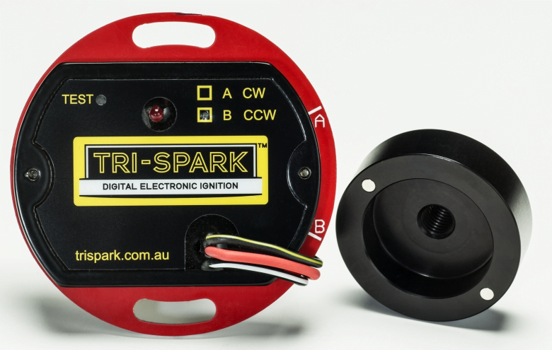
The Tri-Spark unit is a one box solution – all the gubbins are mounted inside the points cover – no additional black box to try and hide under the tank, and very very simple to connect up.
The wiring is as follows:
- Red wire – this is the positive feed to the Tri-Spark unit. Most people attach this wire to one of the two fixing posts inside the points cover. I would personally recommend running an additional wire up to the coils and have drawn it this way on the wiring diagram.
- Black/Yellow – this is the negative feed to the Tri-Spark unit. This joins in to the White/Yellow that is the kill switch on your right side handlebar switch (the Ballast resistor is no longer required)
- Black/White – this is the negative supply FROM the Tri-Spark TO the coil.
You’ll note in the wiring diagrams below that the Ballast Resistor and Condensers have been removed as part of the conversion to Electronic Ignition.
A major benefit of the Tri-Spark is a very low operating voltage – as low as 8 volts means your bike will still run with a less than optimal battery and charging system
Coil
In lieu of the twin 6 volt coils, Mike has chosen to fit a dual output single tower coil.
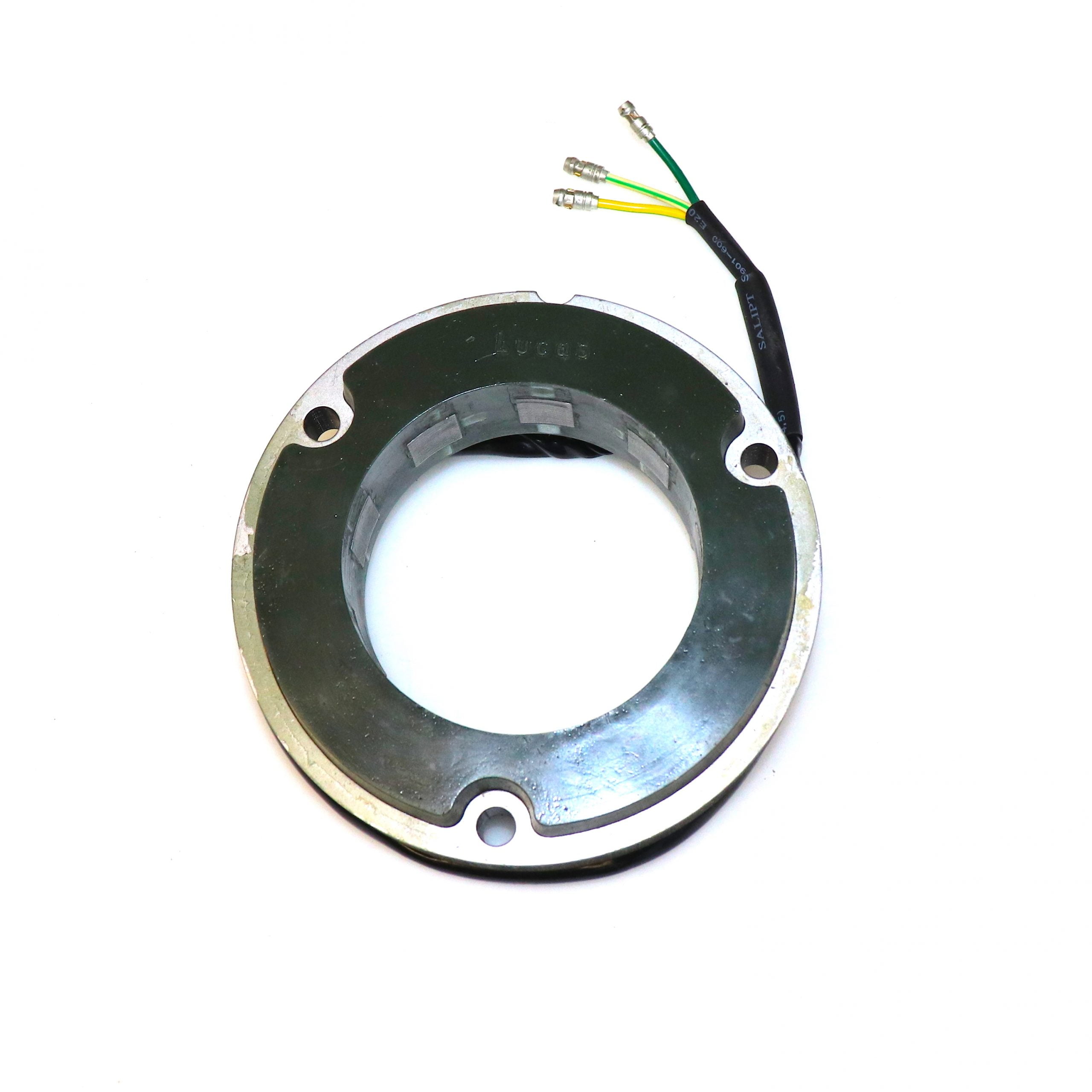
Alternator
Mike has fitted a 3 phase Lucas alternator – a nice choice for superior charging in modern traffic conditions, since the same output is achieved at a much lower RPM
Regulator/Rectifier
To go with the three phase Stator, Mike has fitted a 3 phase MOSFET regulator/rectifier.
The MOSFET unit gives a much cleaner, higher quality output – and is a great pairing for sensitive electronics components like the Tri-Spark ignition and the electronic tacho.
Charge Warning Light
In lieu of there being no unreliable, standard Lucas 3AW 3 wire ‘silver can’ assimilator currently fitted, Mike has gone for an Improving Classic Motorcycles Charge Warning Light.

These give you a lot more useful information about the state of the battery and charging system compared to the standard assimilator unit, which looks for AC output from the alternator stator only.
And to take things one stage further, Mike has chosen to fit the version that contains an input for an oil pressure switch too. What a great idea!

Electronic Tacho
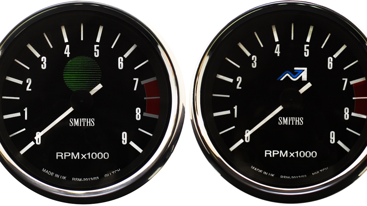
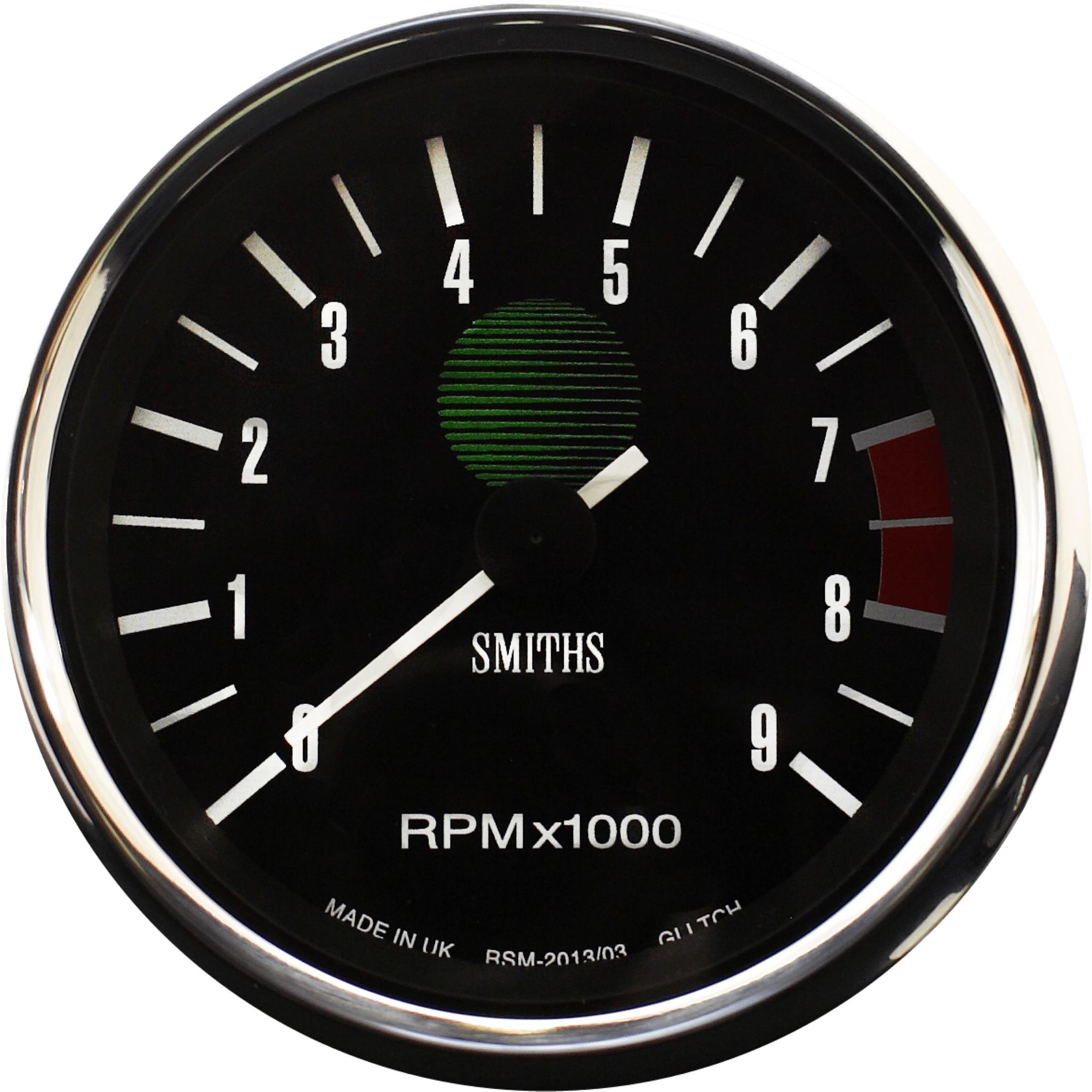
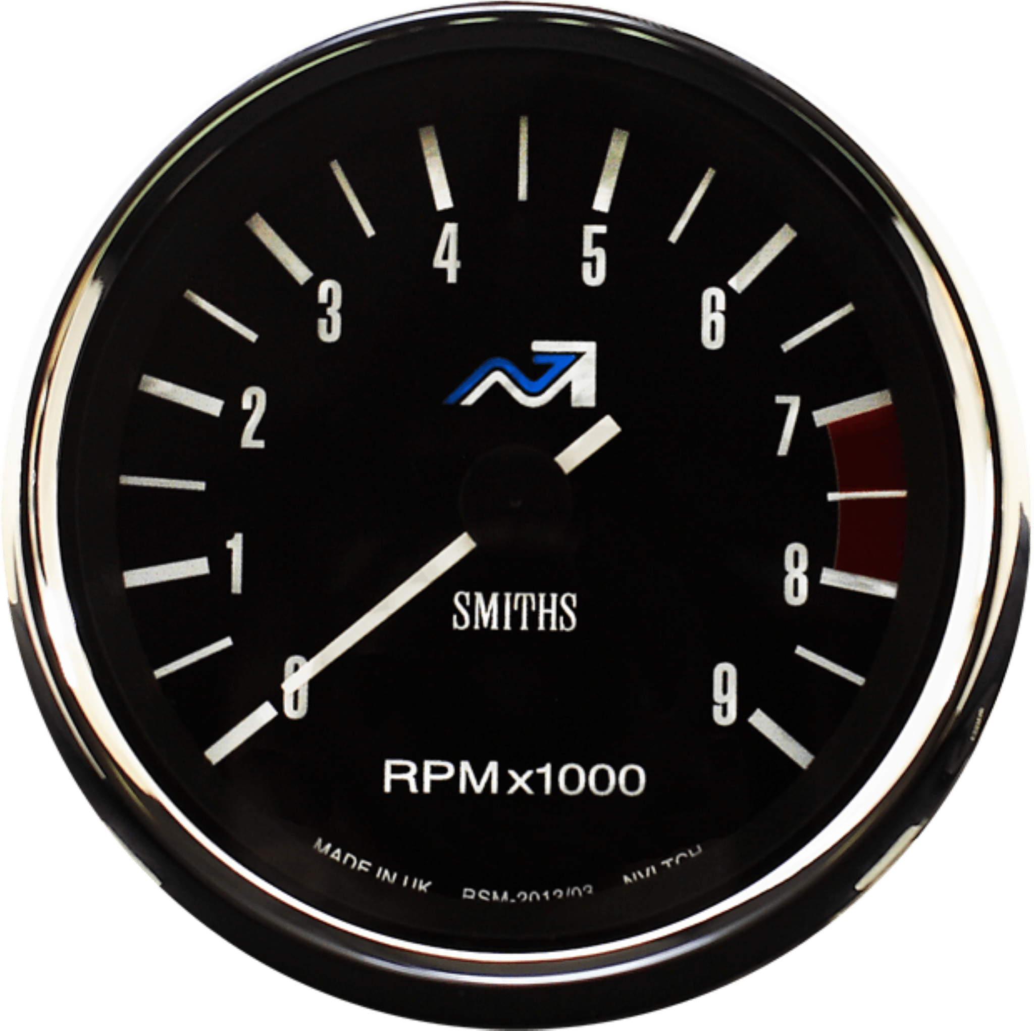
Mike is fitting an electronic tacho to his bike – Smiths make these, and they are a dead ringer for the look of the factory original. They even make them with the Norton green globe or NVT symbol, so you can match them in to the original speedo on the bike.
Fitting an electronic tacho brings a couple of neat benefits to the party – no leaks around the tacho drive that screws into the crankcase (although Andover Norton do make a unit which contains a much improved oil seal which does a good job)
The other benefit in my opinion is there is no longer any need to wrestle with the tacho drive cable – these are always unwieldy and difficult to make them look neat and tidy on the bike – this is even more of the case on the Dominator, Atlas and early 20M3 Commandos where the tacho drive is on the end of the camshaft, mounted on the timing cover.
Wiring an electronic tacho in is simple – just pick up a pulse from the connection between the electronic ignition and the coil.
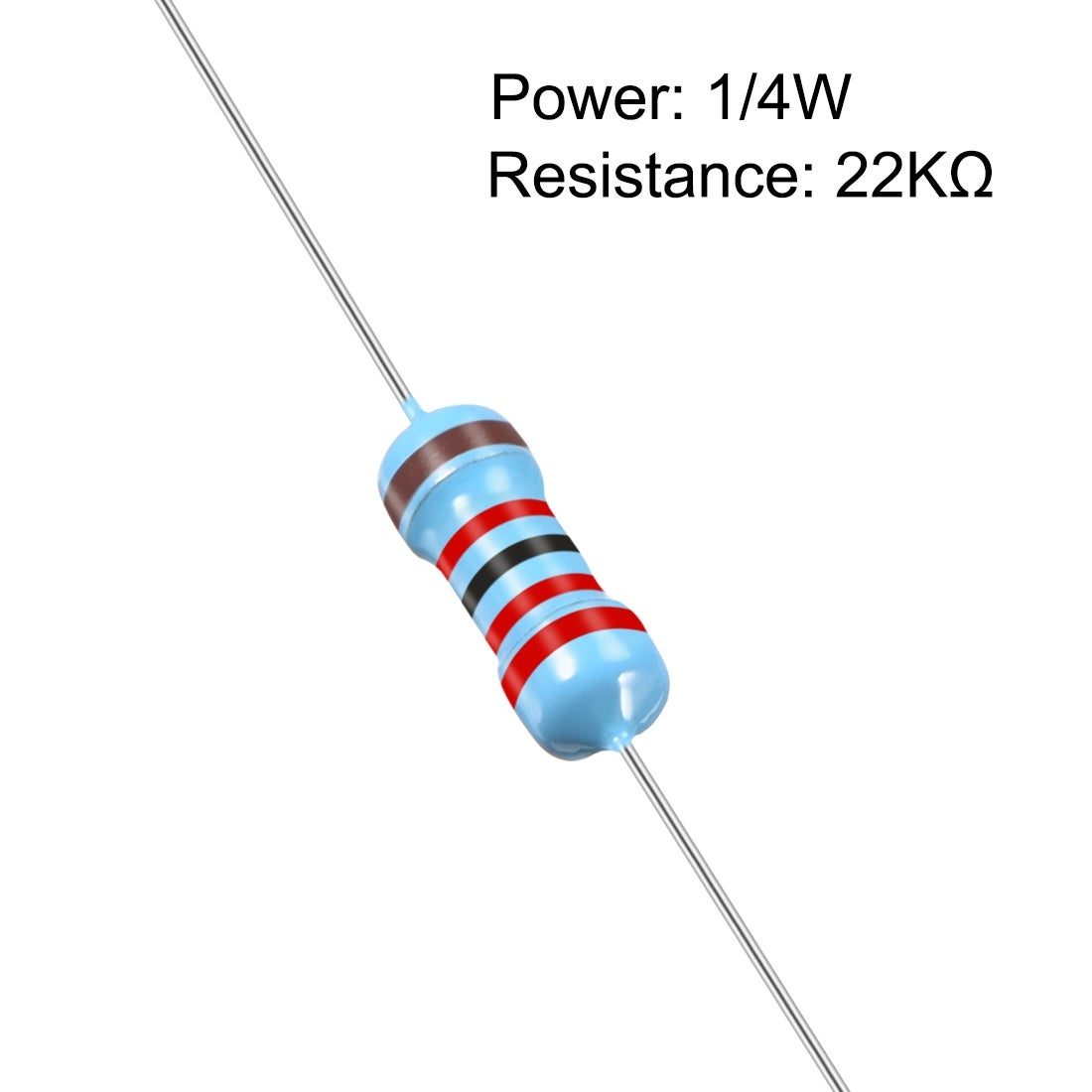
I recommend you fit a resistor – value 22KΩ in this line (labelled Number 3 on my diagram) – Smiths were providing these in the box when you buy a tacho at one point in time – I am not sure whether they still are or not.
Here are the instructions for installing the Smiths Tacho – together with my scribbles over the top – hopefully making things easier to understand.
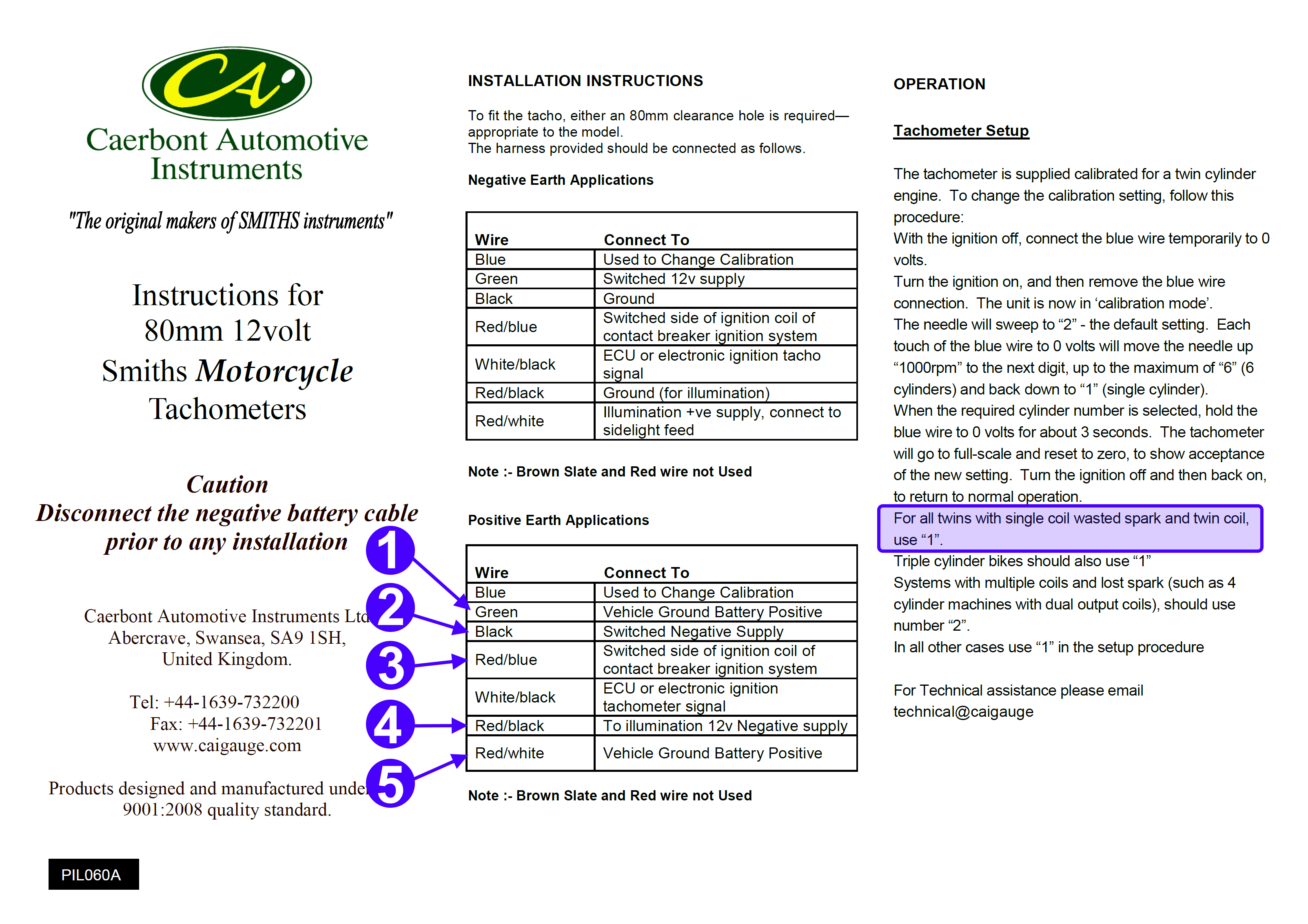
The circled numbers on the Installation Instructions pick up on the below wiring diagram:
- 1 & 5 any red wire to positive feed in the headlight bucket – you have a spare, that used to go to the backlight on the old analogue Smiths gauge.
- 2 any white wire inside the headlight bucket – this is the ‘hot’ negative that is switched on and off with the ignition key.
- 3 this is the trigger that provides the pulse – the negative wire that runs between the electronic ignition and the coil. This is the one that should have the resistor inline.
- 4 any brown/green in the headlight bucket – you freed up a spare when you took out the old analogue gauge. This is the negative that switches on and off with the pilot light/tail light.
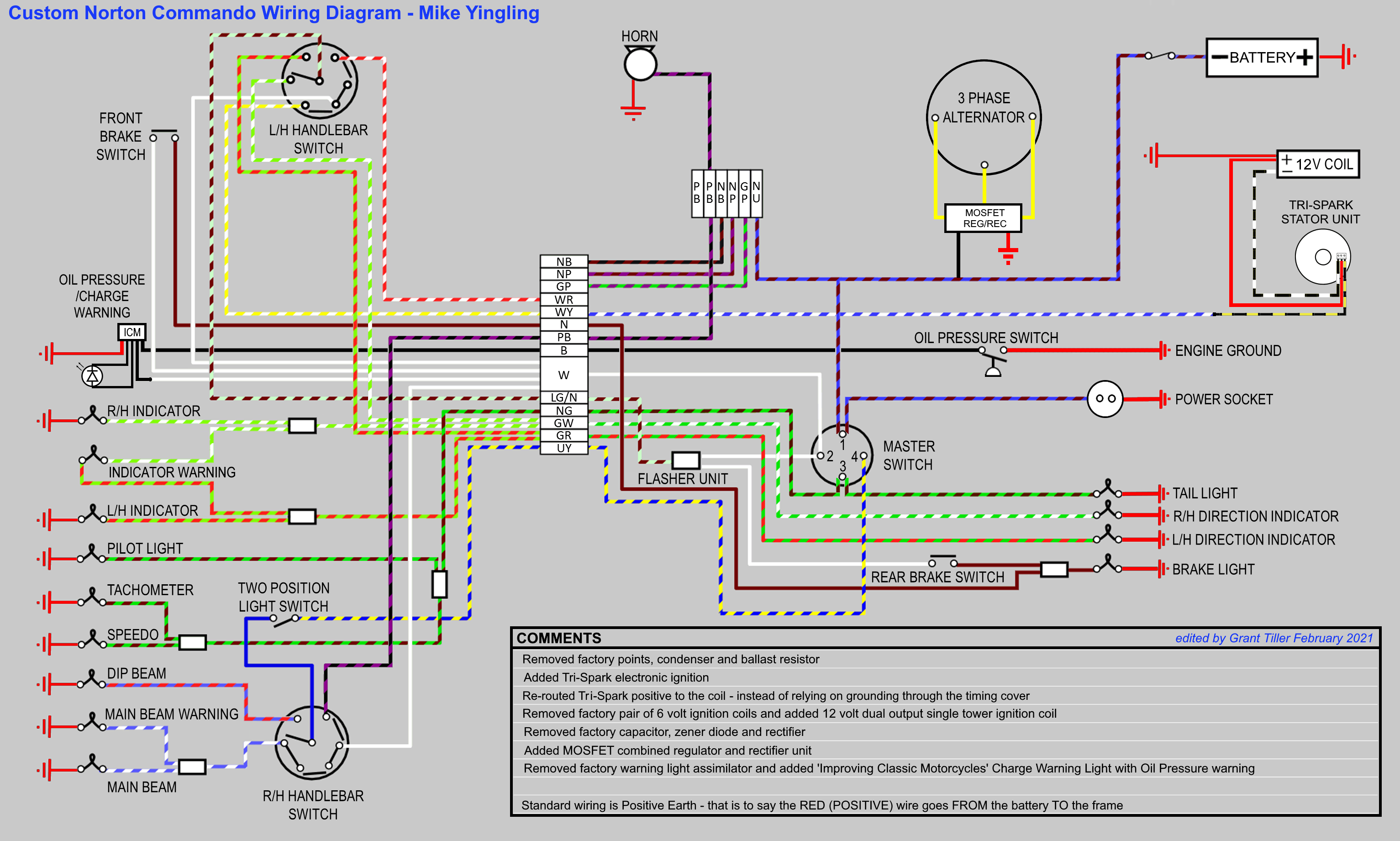
Wiring Diagram
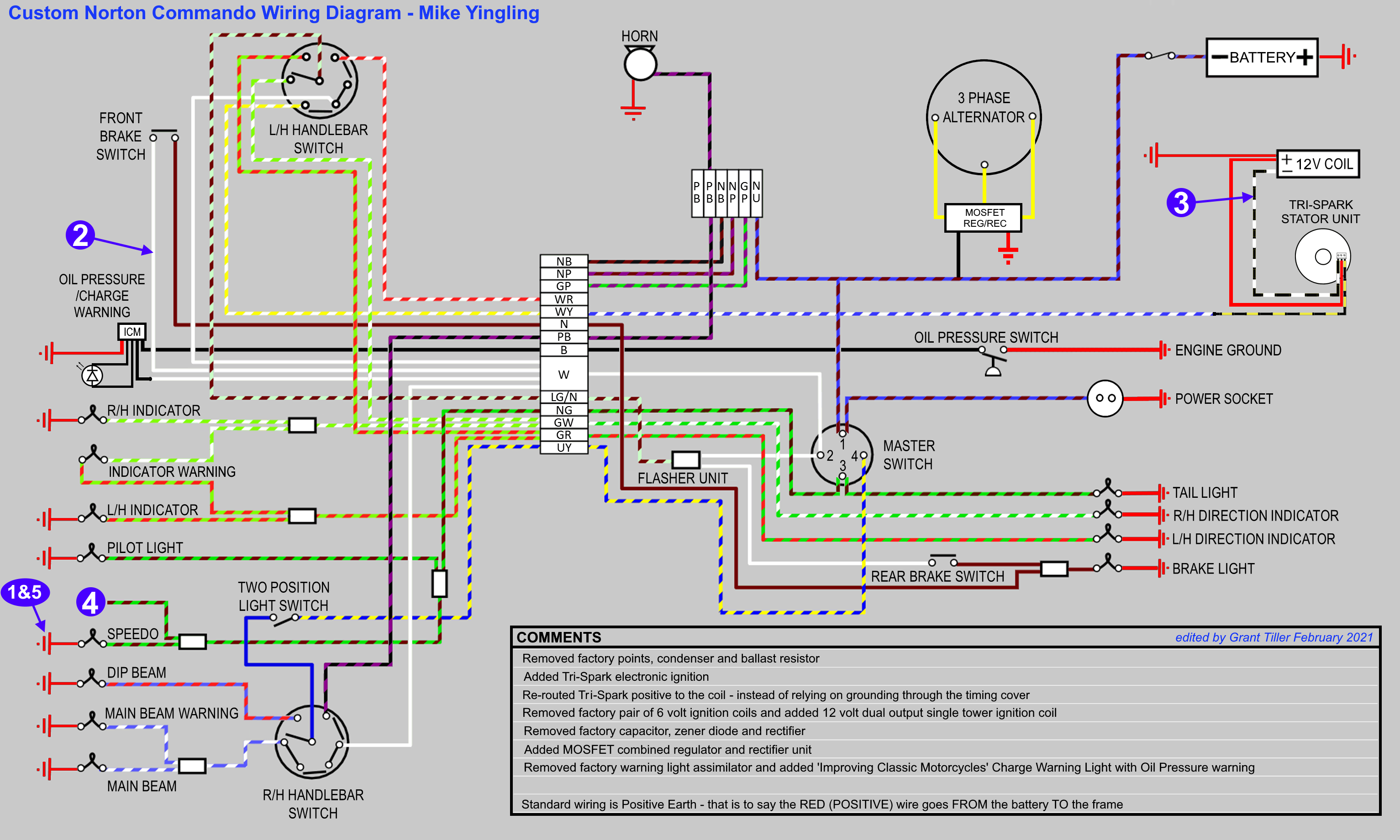
Here is the wiring diagram for Mike’s bike.
Custom Norton Commando Wiring Diagram – Mike Yingling PNG 3066×1841