

Sparx was setup by Andy Gregory – the Triumph Parts Specialist – AKA Tricor Andy
Personally, I am not a big fan of Andy, or Sparx – having received very poor customer service from him in the past when trying to fix someone’s Triumph Bonneville wiring issues.
Sparx are also known for their aftermarket handlebar switches too.

I fitted a Sparx 3 phase high output alternator to a 1965 Triumph Bonneville T120 and wasn’t overly impressed.
The hole through the rotor was too small to fit over the crankshaft.
When questioned, I was told this was by design and that it should be broached on to the crankshaft by ‘whacking it on with a mallet’ then ‘graunching up’ the retaining nut.
That’s all well and good, but what about the poor guy that needs to get it off in the future?
Instead I used a reamer and reamed the hole out to fit. It was a nice snug fit, just like the Lucas rotors are right out of the box!
The rest of the alternator kit was OK.
Regulator/Rectifier
The regulator/rectifier AC wires were all yellow and the alternator stator wires were green and white, which was a bit weird considering it was supposed to be one kit from one manufacturer – I was surprised they didn’t make an effort to standardise on wire colours.

Not a major issue though, and me just being a bit ‘nit picky’
One thing that did surprise me was the Instructions:
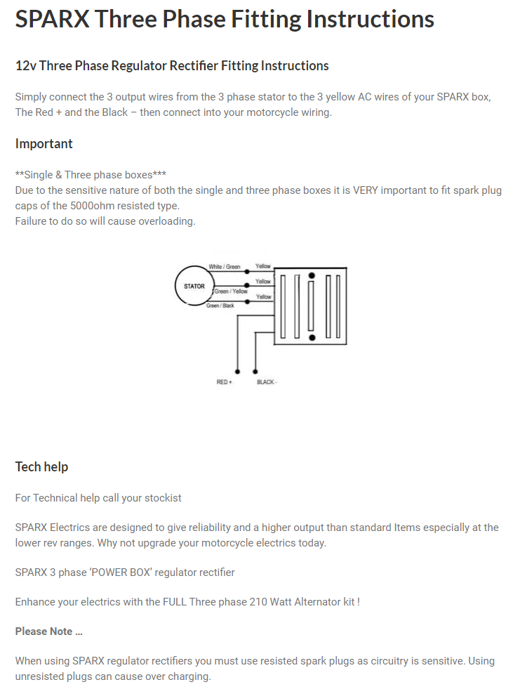
I was surprised that the instructions referred to using 5K resisted spark plug caps at the top of the page and stating that failure to do so will cause overloading.
Then at the bottom of the page it refers to using resisted spark plugs, as circuitry is sensitive and failure to do so will cause over charging.
These are the kind of disclaimers I would expect to see in the documentation of electronic ignitions, where there is a conversion of analogue rotation to a digital trigger signal, which can indeed be susceptible to radio frequency interference (RFI) or electro-magnetic interference (EMI)
Probably a sign here, I feel, that very poor quality components have been used.
There are five wires to connect:
| Wire Colour | Description |
|---|---|
| Yellow (x 3) | these are the AC input and pick up on the Green/Yellow and White/Green (connection can be any way round, as this is the AC side of the circuit) |
| Red | this is the Positive output and will join to the red wire if you are using existing wiring (it goes straight to the ground/earth of the frame) |
| Black | this is the Negative output (known as the hot wire) – it will pick up on the Brown/Blue wire (which goes via a fuse straight to the battery negative terminal) |
Warning Light Assimilator
The factory warning light assimilator is not compatible with most modern regulator/rectifiers so it has been removed from the schematics.
Plus, there is the matter of what the WLA is actually doing, and how much use that is.
The WLA is looking purely for some AC output from the alternator stator (about 6 ½ volts AC) it is not designed for a three phase stator either.
It gives you no information about the charging (i.e., the regulator (zeners) and rectifier)
It gives you no information about the state of the battery.
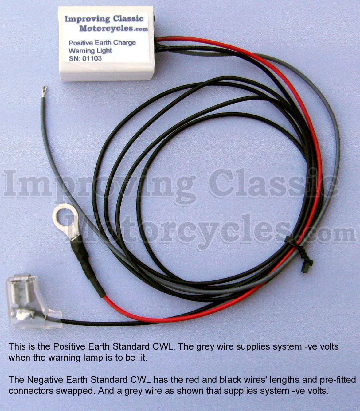
Charge Warning Light

I have taken the liberty of adding an ICM Charge Warning Light to the schematics – I can certainly recommend the Improving Classic Motorcycles charge warning light as a brilliant alternative.
I use them myself, and have had a good experience with them.
The nice thing about the Improving Classic Motorcycles unit is that you can retain the original warning light – so it looks totally factory (this for me is an important factor with the MK3 with it’s quirky little instrument panel).
It gives you a lot more useful information about the state of the battery and charging system compared to the standard assimilator unit, which looks for AC output from the alternator stator only.
Electronic Ignition
These are popular among Triumph owners, but work on Norton Commandos too – they seem to be a Boyer Bransden clone (which is not necessarily a bad thing)

The setup of the Sparx electronic ignition will be familiar to most.
Moving from points to the Sparx electronic ignition is a pretty simple upgrade.
From a wiring perspective, the most important thing to note is that you will be moving from a pair of coils that are wired in parallel to series.
Originally, the points make and break the positive (earth) side of each coil in turn.
The Sparx electronic ignition system uses a concept called “wasted spark” – with the two coils wired in series, they are energized together on every rotation of the camshaft.
You’ll note in the wiring diagrams below that the Ballast Resistor and Condensers have been removed as part of the conversion to Electronic Ignition.
The color coding of the wiring is simple:
| Wire Colour | Description |
|---|---|
| Red | this is the positive feed (earth/ground) to the Sparx, and is usually picked up from the red wire that goes to the Coil positive terminal |
| Black | this is the negative supply FROM the Sparx TO the coils |
| White | this is the negative feed to the Sparx. In this case, we are joining it in to Pin 2 on the Master Switch (ignition key switch) |
| Black/Yellow and Black/White | these go from the Sparx ‘Igniter Box’ down to the Stator Plate in lieu of the old points |
For your information, here is a copy of the instructions that are supplied with the Sparx unit:

1968 Norton Commando Wiring Schematic + Sparx Charging and Ignition
These are the pre-1971 bikes and have the ammeter in the headlight shell, as well as the Wipac Triconsul type handlebar switch.
The wiring is very simple, and more like the Atlas than what came to be familiar with the Commando.
Note that I have included the Front Brake Switch as standard – this was a US requirement, that didn’t appear on the earliest UK bikes.
1968 Norton Commando Wiring Schematic + Sparx Charging and Ignition PNG 5600×3960

This diagram is also downloadable as a PDF from HERE
1971 Norton Commando Wiring Schematic + Sparx Charging and Ignition
This is often referred to as the “Interim” model.
It is distinguishable by the three pin master switch (ignition key switch) which was Lucas part number LU39565.
These were made ONLY for the Norton Commando, and are no available as an aftermarket replacement.
If you are not comfortable rebuilding the switch, most people choose to go for the LU30552, which IS readily available.
You can find an article on ignition switches here, that may be of interest.
1971 Norton Commando Wiring Schematic + Sparx Charging and Ignition PNG 5600×3960

This diagram is also downloadable as a PDF from HERE
1972 onwards Norton Commando Wiring Schematic + Sparx Charging and Ignition
The 1972 onwards schematic covers 750 and 850 bikes and has the much more familiar four pin master switch (ignition key switch)
1972 onwards Norton Commando Wiring Schematic + Sparx Charging and Ignition PNG 5600×3960

This diagram is also downloadable as a PDF from HERE
MK3 Commando
During the manufacture of the MK3, Norton and Triumph were coming together, and they were often feeding from the same parts bins.
We have noted some anomalies between the handlebar switches while the MK3 was in production, as they frequently used the Triumph T140E switches, which look the same, but have a couple of small wiring differences.
Left handlebar switch the U (blue) used by Norton (and illustrated in the factory workshop manual) has been replaced with a UY (blue/yellow) cable. This connects to the U (blue) of the right handlebar switch inside the headlamp bucket.
Right handlebar switch there is no S (slate grey) instead, the single “hot” negative from the pin 2 of the Master Switch (ignition key switch) is jumpered for both engine run/kill switch and the starter button.


Another element of the MK3 that sometimes causes confusion is the wiring around the Warning lights.
The factory workshop manual shows the following:
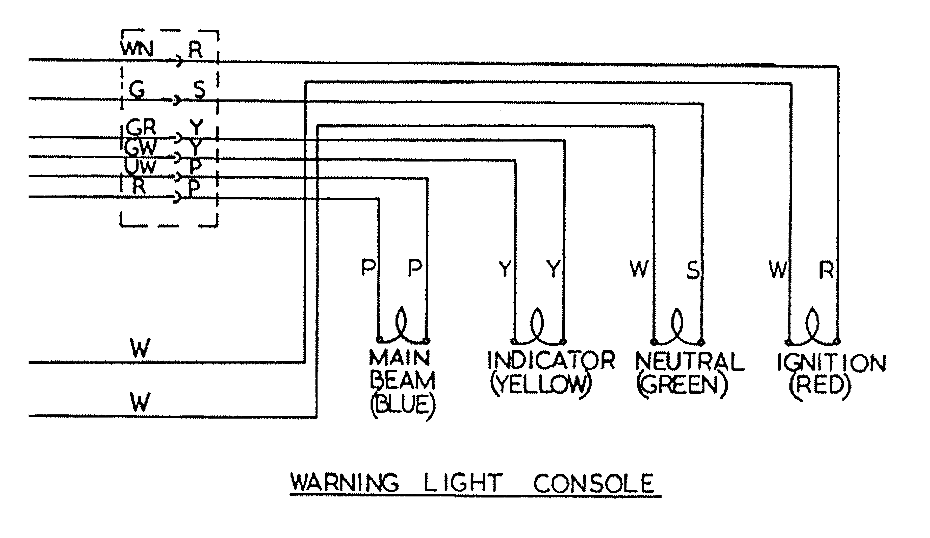
I have covered this in more detail in a separate article, which can be found here.
But in short, the cable colors used for the sub-console wiring harness were not the same all the way through MK3 production – so certainly something to watch out for!
1974 Norton MK3 Commando (Early) Wiring Schematic + Sparx Charging and Ignition
1974 MK3 Early Bikes – there were around 2,000 bikes that were built around the December 1974 timeframe that have three additional fuses that can be found in the headlamp bucket.
1974 Norton MK3 Commando (Early) Wiring Schematic + Sparx Charging and Ignition PNG 5600×3960

This diagram is also downloadable as a PDF from HERE
1975 Norton MK3 Commando Wiring Schematic + Sparx Charging and Ignition
This is the most common configuration, and takes us through to the final Commando that rolls off the production line.
1975 Norton MK3 Commando Wiring Schematic + Sparx Charging and Ignition PNG 5600×3960

This diagram is also downloadable as a PDF from HERE
1975 Norton MK3 Commando (Canadian Market) Wiring Schematic + Sparx Charging and Ignition
For the Canadian Market, there were legal requirements around the headlamp being on while the engine was running.
A different Master Switch (ignition key switch) is fitted in order to adhere to law in Canada. More info is available here in a separate article.
This is covered in the Factory Wiring Diagram, by notes.
The Canadian key switch LU30825 is not available, and must be rebuilt manually.
1975 Norton MK3 Commando (Canadian Market) Wiring Schematic + Sparx Charging and Ignition PNG 5600×3960

This diagram is also downloadable as a PDF from HERE
NOTE:
A couple of points about the way these diagrams have been drawn:
- The diagrams on my site are schematics – the components are not drawn in the physical location on the bike. Instead they are drawn in locations that make the diagram the easiest and most logical to follow.
- Where the same colour wire goes in to and out of a single connector, that connector has usually been omitted from the drawing.
It’s obvious on the bike, is easy to spot and easy to troubleshoot.
Leaving them off the diagrams makes them a LOT easier to read, and considerably less cluttered. - Wherever the earth or ground side of a component goes back to the battery, the drawing shows a red earth symbol:

In reality, this could be connected either to a red wire in the bike’s wiring harness (loom) OR it could be attached to the frame or engine of the bike.
I have shown the red earth symbol each time in order to massively simplify the diagram, and make it a lot easier to understand for everyone.
I have also coloured them red as a gentle reminder that these bikes are wired positive earth!
Ah, yes Tricor Andy. We were one of the largest Sparks and Tricor distributors in the US until about 2013. When I got into this business in 2005 my first task assigned to me was hand reaming a mountain of undersized alternator rotors. Years later I would be in charge of purchasing and would approach vendors with product issues. In the whole time we sold Sparx products we never received any compensation for parts we had to warranty for customers. Not for the several hundred 30552 ignition switches without internal stop. Not for the bar switches that the vacuum carding machine broke the paddle off. We finally lost our distributor status after having nearly a dozen three phase units fail in a month. Some issue with the Sparx regulator back feeding and over heating one of the phase windings. Every third pole had scorched epoxy so it was not a friction burn. We were told to hit the road because we “were not supporting the product”. After this we approached Emgo to produce the three phase alternator that they sell to this day.
Great to hear from you Nick!
Yes, your comments are 100% in line with my own experience, and that of several people I have help out over the years.
Alas, it doesn’t appear that feedback has helped their quality, as only last week I heard about someone’s disappointment around the Sparx T140E/Commando handlebar switches.
It’s such a shame.