


Several people are looking at the Electrex World STK-102D-DC kit with a view to fitting to their Commando.
Proceed with caution – it’s not a simple swap, and you may not be getting what you are expecting from the solution.
Here is a copy of the Electrex World STK-102D-DC instructions:

Here is a copy of the Electrex World STK-102D-DC troubleshooting guide:

The CDI unit is manufactured by Horse Power Ignition
Here is a copy of the HPI 068C041 CDI unit instructions:

There is a great video on YouTube which was made by Classic British Spares
You can see the video by clicking here:

Warning Light Assimilator
The factory warning light assimilator is not compatible with most modern regulator/rectifiers and while there is no mention of it on the Electrex site, I assume this is the case here.
So I have removed it from the schematics.
Plus, there is the matter of what the WLA is actually doing, and how much use that is.
The WLA is looking purely for some AC output from the alternator stator (about 6 ½ volts AC) it is not designed for a three phase stator either.
It gives you no information about the charging (i.e., the regulator (zeners) and rectifier)
It gives you no information about the state of the battery.
Charge Warning Light

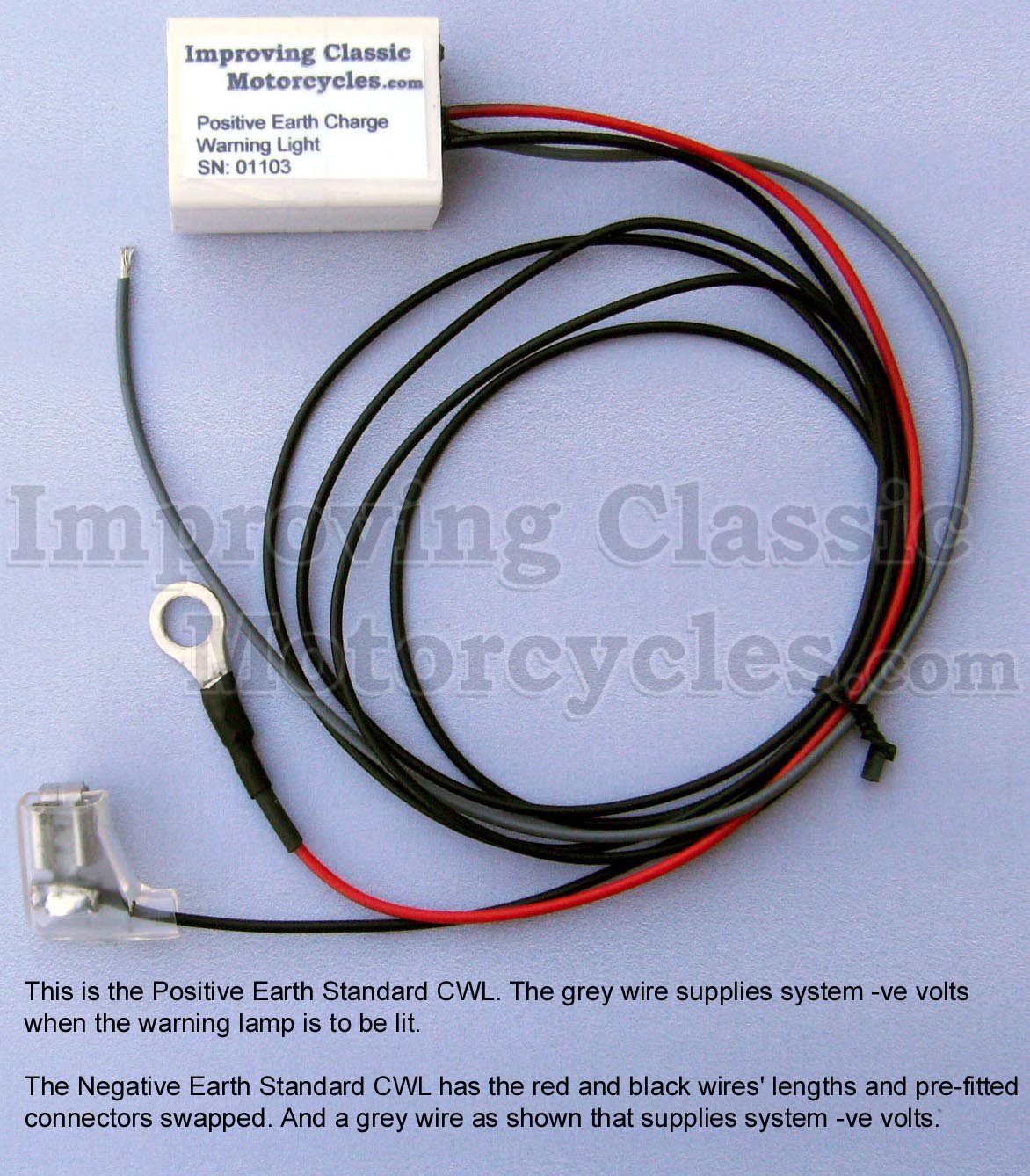
I have taken the liberty of adding an ICM Charge Warning Light to the schematics – I can certainly recommend the Improving Classic Motorcycles charge warning light as a brilliant alternative.
I use them myself, and have had a good experience with them.
The nice thing about the Improving Classic Motorcycles unit is that you can retain the original warning light – so it looks totally factory (this for me is an important factor with the MK3 with it’s quirky little instrument panel).
It gives you a lot more useful information about the state of the battery and charging system compared to the standard assimilator unit, which looks for AC output from the alternator stator only.
Here follows the Norton Commando wiring diagrams – as usual, broken down into Pre-1971, 1971 and 1972 onwards.
I have not included MK3 bikes here – they are very power hungry, and the spec of the alternator in the Electrex kit would not be up to the job.
Hopefully someone will find this useful!
1968 Norton Commando Wiring Schematic + Electrex World CDI ignition and charging
These are the pre-1971 bikes and have the ammeter in the headlight shell, as well as the Wipac Triconsul type handlebar switch.
The wiring is very simple, and more like the Atlas than what came to be familiar with the Commando.
Note that I have included the Front Brake Switch as standard – this was a US requirement, that didn’t appear on the earliest UK bikes.
1968 Norton Commando Wiring Schematic + Electrex World CDI ignition and charging PNG 5600×3960

This diagram is also downloadable as a PDF from HERE

1971 Norton Commando Wiring Schematic + Electrex World CDI ignition and charging
This is often referred to as the “Interim” model.
It is distinguishable by the three pin master switch (ignition key switch) which was Lucas part number LU39565.
These were made ONLY for the Norton Commando, and are no available as an aftermarket replacement.
If you are not comfortable rebuilding the switch, most people choose to go for the LU30552, which IS readily available.
You can find an article on ignition switches here, that may be of interest.
1971 Norton Commando Wiring Schematic + Electrex World CDI ignition and charging PNG 5600×3960

This diagram is also downloadable as a PDF from HERE
1972 onwards Norton Commando Wiring Schematic + Electrex World CDI ignition and charging
The 1972 onwards schematic covers 750 and 850 bikes and has the much more familiar four pin master switch (ignition key switch)
1972 onwards Norton Commando Wiring Schematic + Electrex World CDI ignition and charging PNG 5600×3960

This diagram is also downloadable as a PDF from HERE
NOTE:
A couple of points about the way these diagrams have been drawn:
- The diagrams on my site are schematics – the components are not drawn in the physical location on the bike. Instead they are drawn in locations that make the diagram the easiest and most logical to follow.
- Where the same colour wire goes in to and out of a single connector, that connector has usually been omitted from the drawing.
It’s obvious on the bike, is easy to spot and easy to troubleshoot.
Leaving them off the diagrams makes them a LOT easier to read, and considerably less cluttered. - Wherever the earth or ground side of a component goes back to the battery, the drawing shows a red earth symbol:

In reality, this could be connected either to a red wire in the bike’s wiring harness (loom) OR it could be attached to the frame or engine of the bike.
I have shown the red earth symbol each time in order to massively simplify the diagram, and make it a lot easier to understand for everyone.
I have also coloured them red as a gentle reminder that these bikes are wired positive earth!