


One of the most common upgrades or modifications for a classic british bike is to add a combined regulator/rectifier unit.
Our Commandos use a blue can capacitor, zener diode (which can be found mounted on the back of the z-plate) and rectifier unit.
A combined regulator/rectifier replaces all of these components with one package.
The most common manufacturer of these is PODtronics.

There are four wires to connect:
| Wire Colour | Description |
|---|---|
| Yellow (x 2) | these are the AC input and pick up on the Green/Yellow and White/Green (connection can be any way round, as this is the AC side of the circuit) |
| Red | this is the Positive output and will join to the red wire if you are using existing wiring (it goes straight to the ground/earth of the frame) |
| Black | this is the Negative output (known as the hot wire) – it will pick up on the Brown/Blue wire (which goes via a fuse straight to the battery negative terminal) |
Warning Light Assimilator
The factory warning light assimilator is not compatible with most modern regulator/rectifiers and the PODtronics is no exception so it has been removed from the schematics.
Plus, there is the matter of what the WLA is actually doing, and how much use that is.
The WLA is looking purely for some AC output from the alternator stator (about 6 ½ volts AC) it is not designed for a three phase stator either.
It gives you no information about the charging (i.e., the regulator (zeners) and rectifier)
It gives you no information about the state of the battery.
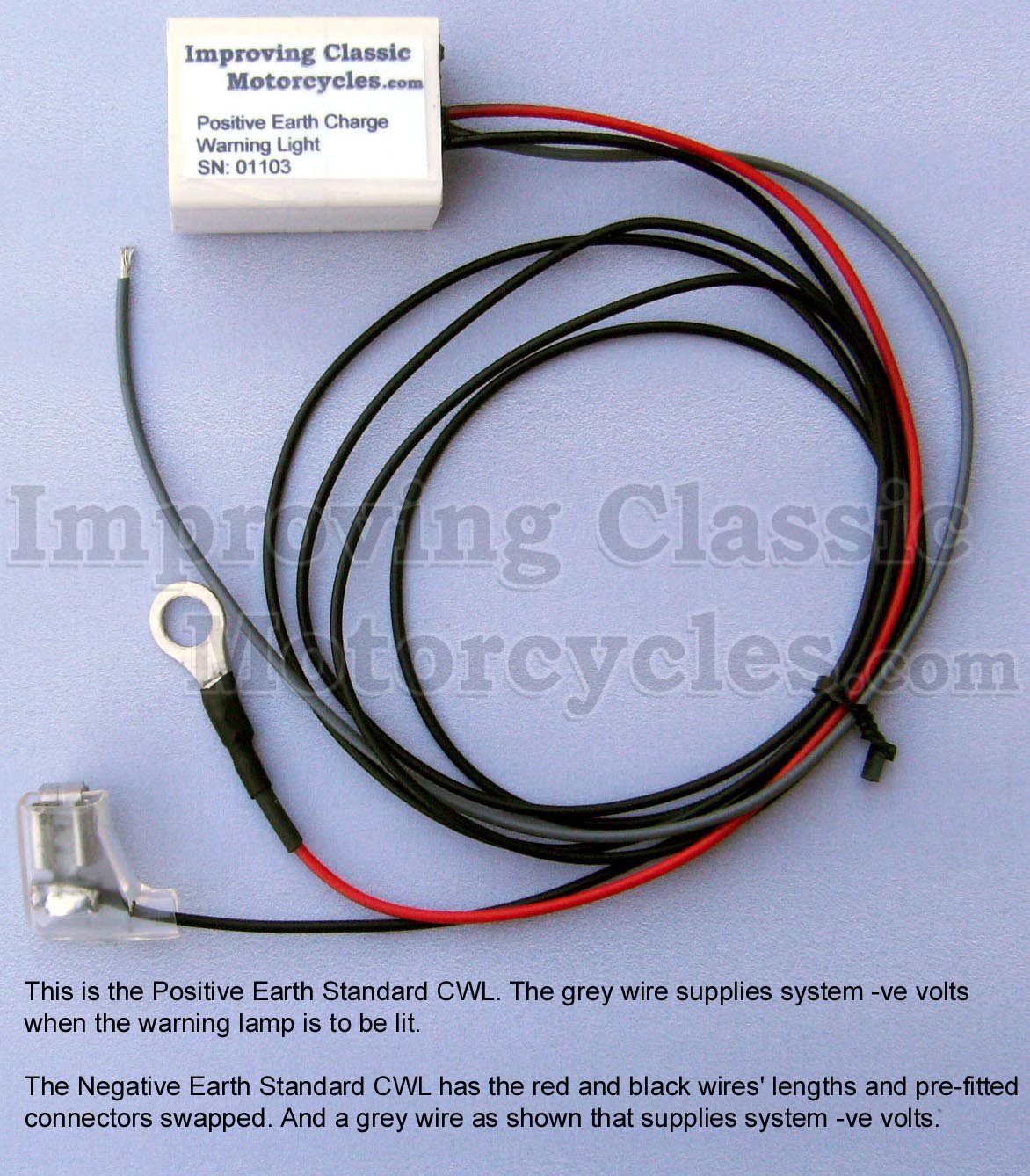
Charge Warning Light

I have taken the liberty of adding an ICM Charge Warning Light to the schematics – I can certainly recommend the Improving Classic Motorcycles charge warning light as a brilliant alternative.
I use them myself, and have had a good experience with them.
The nice thing about the Improving Classic Motorcycles unit is that you can retain the original warning light – so it looks totally factory (this for me is an important factor with the MK3 with it’s quirky little instrument panel).
It gives you a lot more useful information about the state of the battery and charging system compared to the standard assimilator unit, which looks for AC output from the alternator stator only.
1968 Norton Commando Wiring Schematic + PODtronics Regulator/Rectifier
These are the pre-1971 bikes and have the ammeter in the headlight shell, as well as the Wipac Triconsul type handlebar switch.
The wiring is very simple, and more like the Atlas than what came to be familiar with the Commando.
Note that I have included the Front Brake Switch as standard – this was a US requirement, that didn’t appear on the earliest UK bikes.
1968 Norton Commando Wiring Schematic + PODtronics Regulator/Rectifier PNG 5600×3960

This diagram is also downloadable as a PDF from HERE

1971 Norton Commando Wiring Schematic + PODtronics Regulator/Rectifier
This is often referred to as the “Interim” model.
It is distinguishable by the three pin master switch (ignition key switch) which was Lucas part number LU39565.
These were made ONLY for the Norton Commando, and are no available as an aftermarket replacement.
If you are not comfortable rebuilding the switch, most people choose to go for the LU30552, which IS readily available.
You can find an article on ignition switches here, that may be of interest.
1971 Norton Commando Wiring Schematic + PODtronics Regulator/Rectifier PNG 5600×3960

This diagram is also downloadable as a PDF from HERE
1972 onwards Norton Commando Wiring Schematic + PODtronics Regulator/Rectifier
The 1972 onwards schematic covers 750 and 850 bikes and has the much more familiar four pin master switch (ignition key switch)
1972 onwards Norton Commando Wiring Schematic + PODtronics Regulator/Rectifier PNG 5600×3960

This diagram is also downloadable as a PDF from HERE
MK3 Commando
During the manufacture of the MK3, Norton and Triumph were coming together, and they were often feeding from the same parts bins.
We have noted some anomalies between the handlebar switches while the MK3 was in production, as they frequently used the Triumph T140E switches, which look the same, but have a couple of small wiring differences.
Left handlebar switch the U (blue) used by Norton (and illustrated in the factory workshop manual) has been replaced with a UY (blue/yellow) cable. This connects to the U (blue) of the right handlebar switch inside the headlamp bucket.
Right handlebar switch there is no S (slate grey) instead, the single “hot” negative from the pin 2 of the Master Switch (ignition key switch) is jumpered for both engine run/kill switch and the starter button.


Another element of the MK3 that sometimes causes confusion is the wiring around the Warning lights.
The factory workshop manual shows the following:
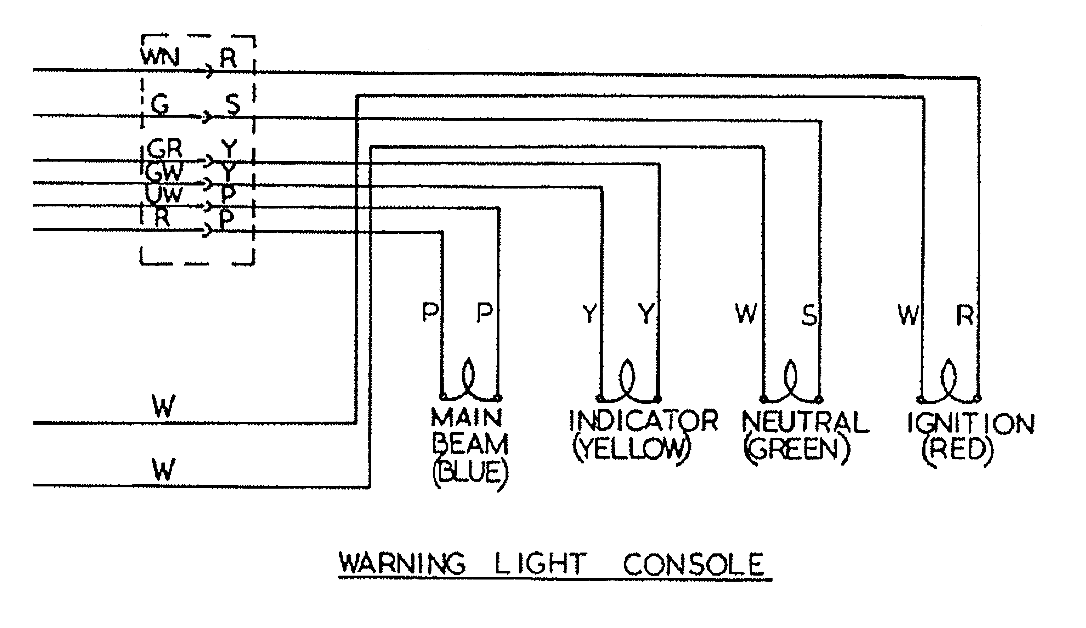
I have covered this in more detail in a separate article, which can be found here.
But in short, the cable colors used for the sub-console wiring harness were not the same all the way through MK3 production – so certainly something to watch out for!
1974 Norton MK3 Commando (Early) Wiring Schematic + PODtronics Regulator/Rectifier
1974 MK3 Early Bikes – there were around 2,000 bikes that were built around the December 1974 timeframe that have three additional fuses that can be found in the headlamp bucket.
1974 Norton MK3 Commando (Early) Wiring Schematic + PODtronics Regulator/Rectifier PNG 5600×3960

This diagram is also downloadable as a PDF from HERE
1975 Norton MK3 Commando Wiring Schematic + PODtronics Regulator/Rectifier
This is the most common configuration, and takes us through to the final Commando that rolls off the production line.
1975 Norton MK3 Commando Wiring Schematic + PODtronics Regulator/Rectifier PNG 5600×3960

This diagram is also downloadable as a PDF from HERE
1975 Norton MK3 Commando (Canadian Market) Wiring Schematic + PODtronics Regulator/Rectifier
For the Canadian Market, there were legal requirements around the headlamp being on while the engine was running.
A different Master Switch (ignition key switch) is fitted in order to adhere to law in Canada. More info is available here in a separate article.
This is covered in the Factory Wiring Diagram, by notes.
The Canadian key switch LU30825 is not available, and must be rebuilt manually.
1975 Norton MK3 Commando (Canadian Market) Wiring Schematic + PODtronics Regulator/Rectifier PNG 5600×3960

This diagram is also downloadable as a PDF from HERE
NOTE:
A couple of points about the way these diagrams have been drawn:
- The diagrams on my site are schematics – the components are not drawn in the physical location on the bike. Instead they are drawn in locations that make the diagram the easiest and most logical to follow.
- Where the same colour wire goes in to and out of a single connector, that connector has usually been omitted from the drawing.
It’s obvious on the bike, is easy to spot and easy to troubleshoot.
Leaving them off the diagrams makes them a LOT easier to read, and considerably less cluttered. - Wherever the earth or ground side of a component goes back to the battery, the drawing shows a red earth symbol:

In reality, this could be connected either to a red wire in the bike’s wiring harness (loom) OR it could be attached to the frame or engine of the bike.
I have shown the red earth symbol each time in order to massively simplify the diagram, and make it a lot easier to understand for everyone.
I have also coloured them red as a gentle reminder that these bikes are wired positive earth!
Hi Grant, many thanks for making these great wiring diagrams available to us, much appreciated.
Just wondering if you could please do one for me that shows 3 phase alternator, Podtronics unit, Tri Spark ign and Colorado Norton Works single double output coil? I would be grateful if you could do this for me
Kind regards
Richard
New Zealand
Hi Richard,
Happy to do a custom diagram for you.
You have removed your Canadian spec Headlamp Warning unit, and use a SparkBright battery monitor.
So did you just cross the blue for the headlamp switch with the brown/green and retain the Canada specific master switch?
Or have you used a standard (rest of world) master switch and wired it the normal way?
Let me know, and I’ll get a diagram up for you!
Hi Richard,
You can find a Custom wiring diagram for your MK3 Commando here:
https://granttiller.com/custom-norton-commando-wiring-diagram-richard-dodds
Regards,
Grant
.Hello Grant
Your schematic, 1975 mk3 to include the PODtronics RR is a beautiful thing, only wish I had looked for it a month ago when I rewired my 1977 mk3 using ‘Lucas’ harnesses, I would have certainly been inclined to make my own loom if I had seen this schematic first. However, I am where I am and I have laminated this schematic to aid me in a final fit for purpose check.
Having discovered that there are a number of wires not required for an updated installation to include items like the ICM which I had already chosen to install and having omitted a bridge on the removed capacitor wires first time around, I was wondering if you had a schematic as drawn but to include a Pazon electronic ignition? My library would then be complete.
If I have contradicted myself at all it’s probably because I purchased the mk3 as a retirement present and have never rewired a bike before. All new 12v wilderness.
All the best
Hi Ian – it’s great to hear from you and thank you so much for your kind words!
There are a couple of schematics that maybe of interest to you:
Pazon Sure-Fire electronic ignition AND PODtronics regulator/rectifier
Pazon Sure-Fire electronic ignition AND PODtronics regulator/rectifier AND three phase alternator stator
Hope this helps!
Grant
Hi Grant can you tell me if the podtronics CS 4035 I I have on my 1975 Norton commando Mark 3 with single phase 180 watt alternator is compatible with the newer solid state assimilator 06.6393. it contains a single transistor and monitors both alternator outputs against the system voltage. I can send a schematic if needed.
Thank you
Hi John,
The PODtronics CS-4035 is the 200 watt single phase reg/rec which is also more commonly sold under the part number POD-1P-HP.
None of the PODtronics units are compatible with any of the original warning light assimilators (neither the pre-MK3 silver-can 1AW or the later MK3 06-6393)
However, the likes of Andover are now selling modern alternatives to these, which are silicon-based solid state devices.
In the case of the MK3 assimilator, although the are sold under the same part number 06.6393 these new units can be distinguished by the fact that they are a slightly larger package, and do not fit in the original location as nicely.
These are compatible with the PODtronics reg/rec.
While they are compatible, I personally find an assimilator almost useless – all it is doing is telling you there is some output from the AC stator. It provides no clues about conversion to DC, whether the output is enough, or the state of the battery.
I prefer the Improving Classic Motorcycles “Standard” charge warning light
It is very simply wired in, and you can retain the original lamp – so it looks totally factory (this for me is an important factor with the MK3 with it’s quirky little instrument panel).
It gives you a lot more useful information about the state of the battery and charging system compared to the standard assimilator unit, which looks for AC output from the alternator stator only.
I have no affiliation with Graham at ICM, I am a customer that pays full price. I merely recommend his units because I use them myself, I like them, and have never had a single failure.
Hope this helps!
Hi Grant
Thank you so much for the very detailed reply. The 06.6393 (5 pin encapsulated unit) worked for 4 years with the podtronics CS 4035 I. The top is 3.6 by 5.1 cm, figure 1 below (I dont have the depth since I destroyed trying to do a post mortem on it). One day a few weeks ago the warning light came on although the output of the podronics was still in exactly the same range of about 12.5 volts at idle and up to 14.2 or so at higher RPM. I assumed it was the 6393 and ordered one from eBay https://ebay.us/m/uA1Gy8 which is another encapsulated unit that looks the same but is 3.4 x 5cm on the top which is a bit smaller and 2.5cm deep , also in Figure 1 on right. I thought all the 6393 units had the single transistor solid state circuit shown in figure 2. I was wondering if you knew what was in the older one that made it incompatible? Did I indeed have the older one and blew it out?
I did measure RMS voltage and current out of the disconnected alternator and it produced 14 volts and 10 amps at 3,000 RPM and 16 volts and 10 amps at 4,000 RPM with my variable load resistor.
I am familiar with the cwl from ICM and they are seem to be a better solution. I have messaged Grant and the trip voltage is 12.5 which should keep it off except at idle and perhaps when the turn signals blink. I would like to use the new 6393 since I already have it. I also have a small voltmeter on the bike.
Final note, the new 6393 had a very high RPM to turn the light off so I added a 20 home resistor in series with the Earth so now it is off except for a very slow idol.
Figure 1
IMG_20250920_170150395.jpg
Figure 2
IMG_20250920_170252464.jpg
Don’t know if the images came through but I also sent you an email earlier with the images intact
Best Regards,
John
dear Sir
wish to change my original rctifier zoner diode system on my Atlas 750 1968 to a modern solid state single phase system like podtronics combined rectifier regulator. The rotor is a lucas 54202298. ignition pazon surefire installed. Will the podtronic 4wire device shown in your instruction work?
sincerely
Peter Lee Dahm
[email protected]
Hi Peter,
Yes it will work absolutely fine.
Click here for a quick modification of the standard Atlas wiring diagram I’ve done to incorporate an aftermarket reg/rec.
Hope this helps!
Grant