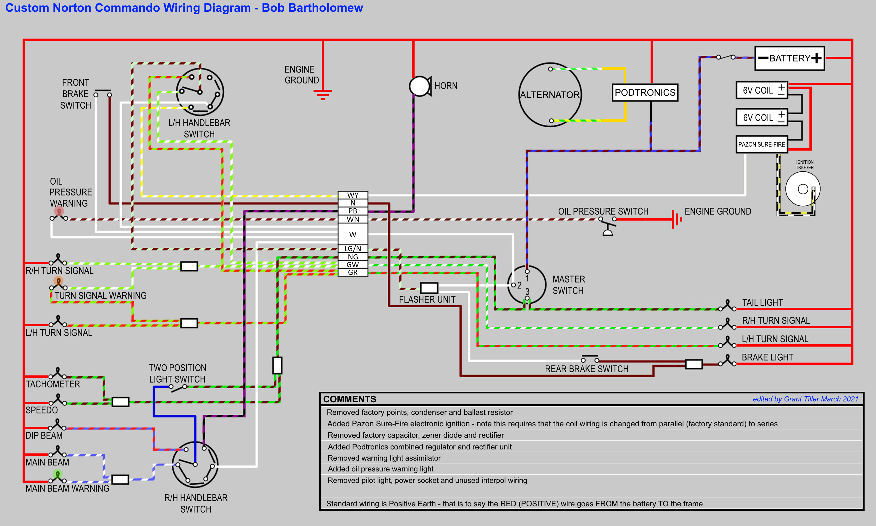
This is Bob Bartholomew’s latest project.
He has rescued a great little 1974 Norton Commando Roadster that has been sat in a basement for nearly forty years!
Bob reached out to initially say thanks for the diagrams up on the site.
He has made a few tweaks of his own, and marked up one of my original diagrams with the alterations.
So I offered to make the changes and post an updated diagram specifically for Bob’s bike.
I just heard from him, and he was on his way to pick up an order from British Wiring – they are great company, so it sounds like he is doing thing right!
Simple
Bob has elected to simplify his wiring – although his Commando is a 1974 model, you’ll see he has fitted a three pin three position) Ignition Switch.
He has also removed the pilot light – opting for dipped beam and main beam up front.
Gone too is the additional wiring for the Interpol flashing lights and horns – fitted to pre-MK3 Commandos, but unused. I always wonder why they made that decision based on the fact that such a small percentage of Norton Commandos became police bikes – it could not have made economic sense!
Warning
Bob has pulled out the Warning Light Assimilator – the Lucas 3AW 3 wire ‘silver can’ assimilator is notoriously unreliable anyway.
They monitor the presence of AC on one of the alternator stator legs, so even when they are in working order, they don’t really tell you much about what your charging system is actually doing.
Bob has, instead, chosen to fit an oil pressure warning light. A very useful addition indeed!
Ignition
A decent Norton Commando upgrade is to move from the old points-based ignition system over to Electronic Ignition.
Bob has fitted a unit that seems really popular these days – the Pazon Sure-Fire

These are popular for two reasons:
- COST – the are one of the lowest price units available on the market at the moment, and the come with an amazing seven and a half year warranty!!!
- RELIABILITY – people are nervous of the ‘shake and bake’ units like the Tri-Spark, where everything is all in one single, miniaturised unit behind the points cover. The Pazon is a carbon copy of the Boyer Bransden unit with a stator plate (Pazon call it the Ignition Trigger) and a separate box of electronics (which Pazon call the Ignition Module)


In fact, the similarities with the Boyer Bransden units don’t end there – all the wires are the same color too!
Actually, Andy and Debbie from Pazon both used to work for Boyer Bransden!!!
Moving from points to a Pazon Sure-Fire electronic ignition is a pretty simple upgrade.
From a wiring perspective, the most important thing to note is that you will be moving from a pair of coils that are wired in parallel to series.
Originally, the points make and break the positive (earth) side of each coil in turn.
The Pazon electronic ignition system uses a concept called “wasted spark” – with the two coils wired in series, they are energized together on every rotation of the camshaft.
You’ll note in the wiring diagrams below that the Ballast Resistor and Condensers have been removed as part of the conversion to Electronic Ignition.
The color coding of the wiring is simple:
- The Red – this is the positive feed to the Pazon, and is usually picked up from the red wire that goes to the Coil positive terminal.
- The Black – this is the negative supply FROM the Pazon TO the coils.
- The White – this is the negative feed to the Pazon. On the older Commandos, this simply picks up the white wire from Pin 2 of the Master Switch.
- Black/Yellow and Black/White – these go from the Pazon Ignition Module down to the Ignition Trigger that sits behind the points cover.
Charging
One of the most common upgrades or modifications for a classic british bike is to add a combined regulator/rectifier unit.
Our Commandos use a blue can capacitor, zener diode (which can be found mounted on the back of the z-plate) and rectifier unit.
A combined regulator/rectifier replaces all of these components with one package.
The most common manufacturer of these is Podtronics.

There are four wires to connect:
- Two Yellows – these are the AC input and pick up on the Green/Yellow and Green/White (connection can be any way round, as this is the AC side of the circuit)
- The Red – this is the Positive output and will join to the red wire if you are using existing wiring (it goes straight to the ground/earth of the frame)
- The Black – this is the Negative output (known as the hot wire) – it will pick up on the Brown/Blue wire (which goes via a fuse straight to the battery negative terminal)
Bob has paired his Podtronics reg/rec up with a Lucas high output RM23 stator.
Wiring Diagram
Here is the wiring diagram for Bob’s bike.
Custom Norton Commando Wiring Diagram – Bob Bartholomew PNG 3066×1841
This is available as a PDF too – it can be downloaded here.