

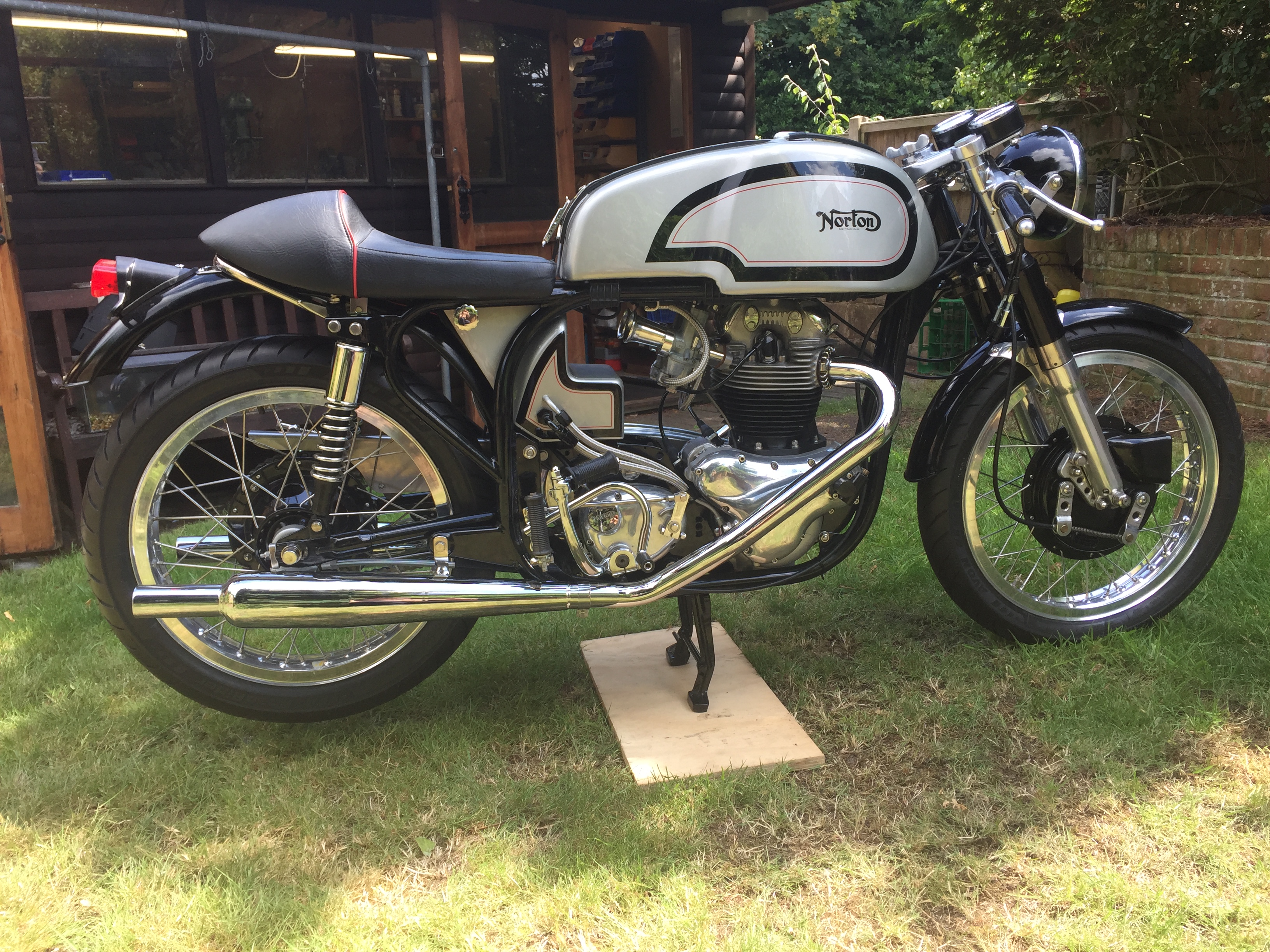
I did a wiring diagram back in December 2021 for a Norton Dommie 650ss, which I simplified down to the very basics.
That article can be found here.
I have been contacted a few times in recent months by people wanting to tweak things a little.
This page covers a magneto bike (as before) but I have removed the key switch in lieu of a kill button on the handlebars as well as eliminated the battery.
So in this scenario, the alternator is directly powering the lighting and horn.
While this article was written based on a 650ss Cafe Racer project, everything covered is true for most brit bikes of the era, so this might be a useful page for non-Norton people too!
Regulator/Rectifier
Planning
As we are removing the battery, there are some things we need to think about.
Adding a capacitor in lieu of the battery is one solution. Many bikes (including the Norton Commando) had a capacitor included in the charging circuit to help smooth out the voltage and to get you home if the battery failed.
That would be absolutely fine with a zener diode handling regulation (the top voltage that can be allowed into the charging circuit) and the original rectifier (the bridge of diodes that converts AC from the alternator to DC that the power consumers require)
However, most aftermarket reg/recs need something different – let me give you some background on how most aftermarket reg/recs work.
An SCR regulator (the most common type) works by sensing the voltage of the battery to determine when to trigger the SCRs that allow the alternator AC voltage to be converted to DC and passed along to the battery to charge it.
If there is no battery present, can we rely on an external capacitor to provide that voltage reading back to the reg/rec?
My view on this is No. We can’t.
A capacitor charges and discharges very rapidly compared to a battery, and has a different voltage curve. This could potentially cause unstable or erratic SCR triggering.
A battery presents a much more stable voltage reference for the sensing circuit to work against.
So what do we do?
With the above in mind, I would recommend against using a capacitor in lieu of a battery when using most aftermarket regulator/rectifiers.
And instead go for a different solution – one that is even simpler in terms of wiring.
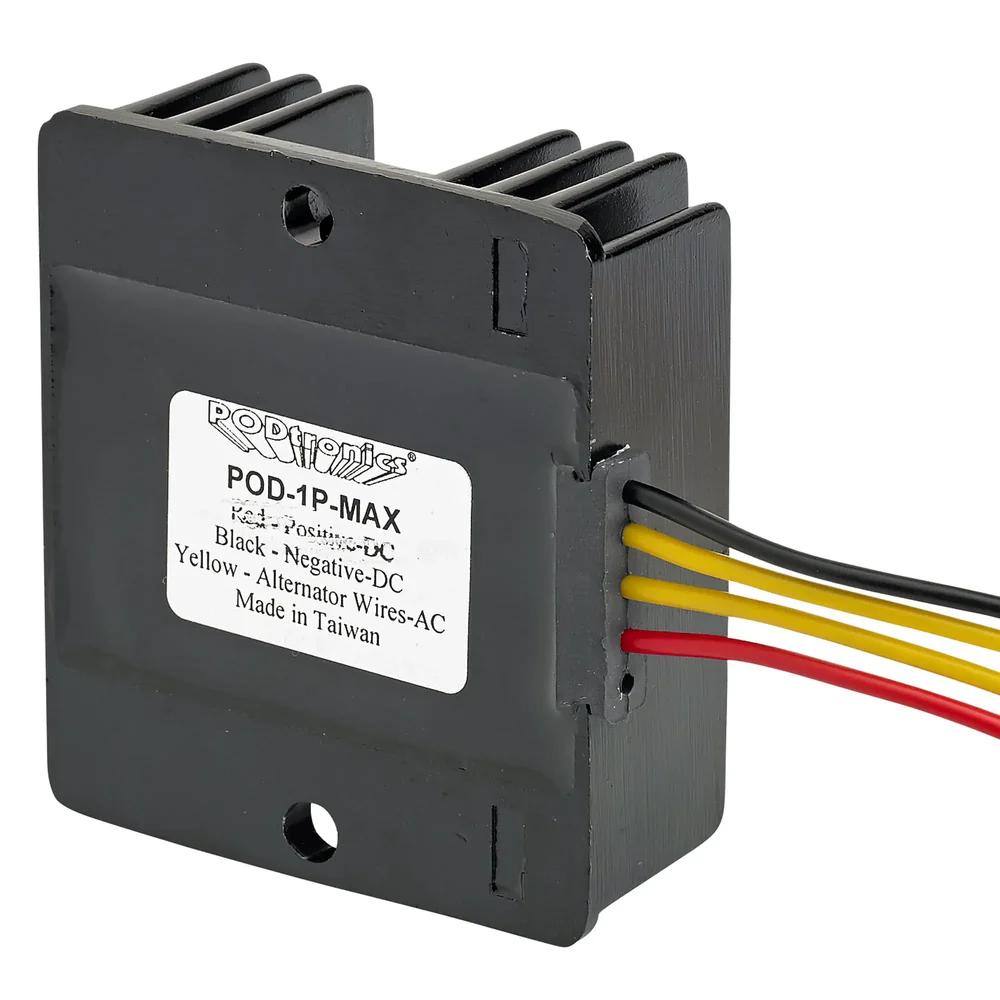
There are vendors that sell “battery eliminator” regulator/rectifiers, which contain a small capacitor within the potted enclosure.
I would recommend going with one of these, if you are determined to do away with the battery, and simplify the electrics on the bike as much as possible.
Two examples of “battery eliminator” regulator/rectifiers are:
- PODtronics POD-1P-MAX
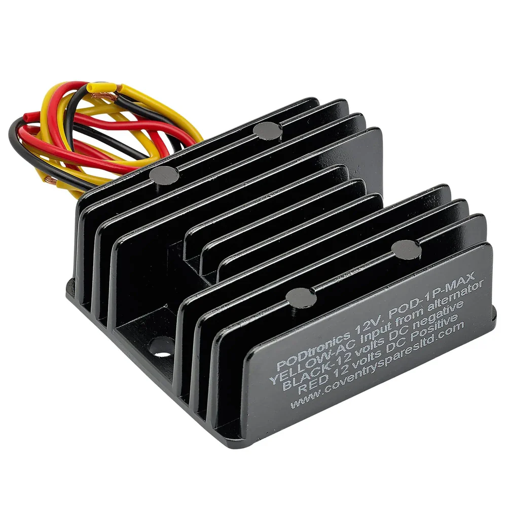
- Boyer Bransden Power Box BOX00108

Using one of the above will allow you to eliminate the battery, and not have to find somewhere for an external capacitor to live.
Tricor Andy also sells one under his Sparx brand – model number SPX023
Other units that were marketed as battery eliminators are Tympanium and Mity Max – I think both of these have disappeared over the years though.
That’s all sorted then!
Yes, you’re good to go with this plan. But there is an important consideration.
I highly recommend that you ride with the headlamp on at all times.
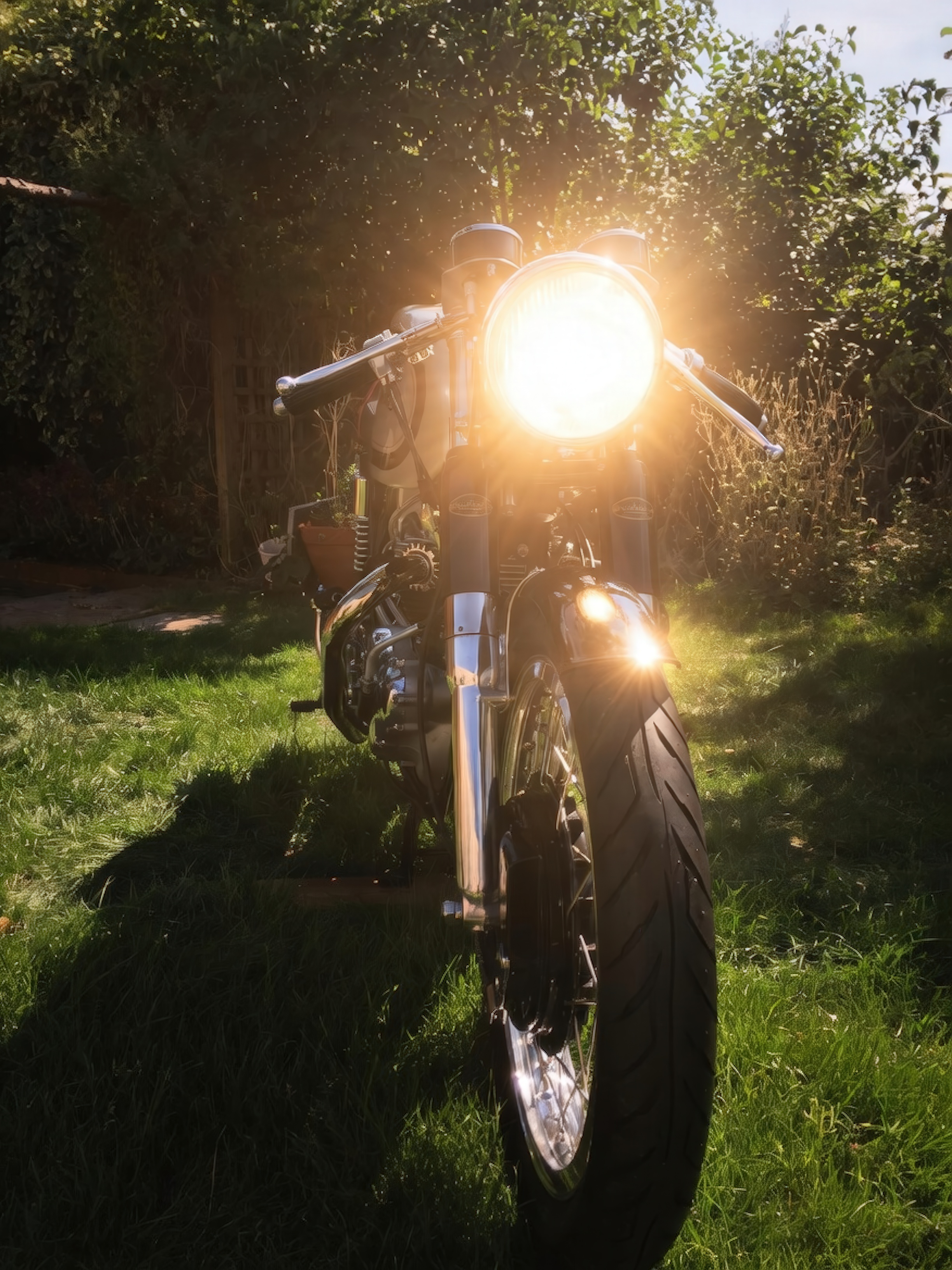
Doing so will provide a constant load and will negate any likelihood of your stator burning out.
We are using a high output stator here, in order to help prevent the lamp brightness “pulsing” at engine idle, so you need to balance the alternator output with the power consumers on the bike as best as you possibly can.
Charging system balance is vitality important, and often overlooked, which results in parts burning out.
Alternator
Unfortunately, we are unable to go for a three phase alternator here. So instead, we are going for a high power single phase unit.
While we don’t need all those amps on such a simple electrical system, we are trying to eliminate the light pulsing that you get at low engine RPM.
This is a compromise, but the best we can do here.
The chances are that your original alternator has seen better days by this point, so if you can, treat yourself to a new stator and rotor.
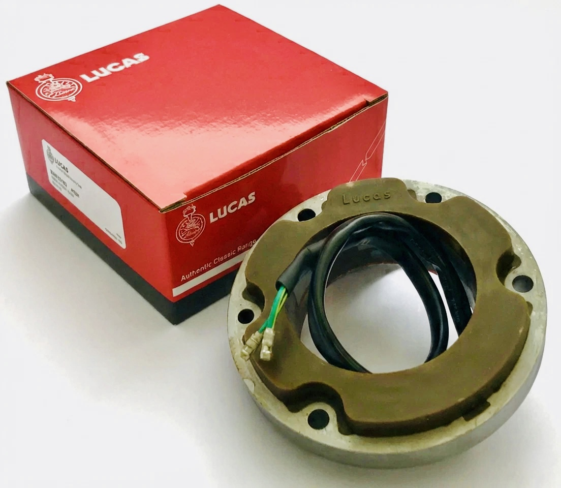
Don’t forget to ride with the headlamp on at all times!
| Lucas Part | Description | Wassell Part | Output |
|---|---|---|---|
| LU47239 | Lucas RM23 Single Phase Stator 2 lead (High Output) | WW10190 | 16 amp |
| __________________ | __________________ | __________________ | __________________ |
Headlight Switch
I went for the standard Lucas toggle switch here – familiar on most bikes of the time, and a very robust and long lasting item.
The LU31788 I use here is a three position Off-On-On switch
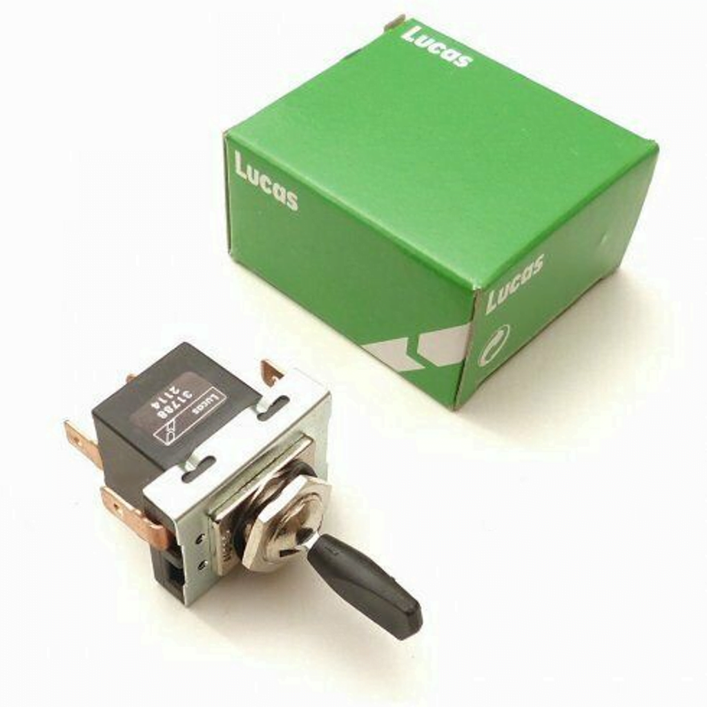
The lights turn on and off via a traditional Lucas 57SA toggle switch mounted on the headlight:
- (1) Off
- (2) Pilot Light
- (3) Dipped Beam
Be careful with part numbers if you are buying new – 57SA is the type (i.e., what it looks like, length of the switch toggle blade, size of mounting hole etc)
Here are the pinouts for the switch in the different positions:
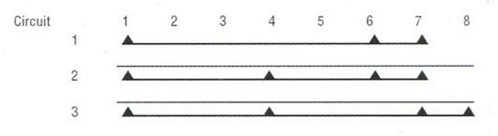
There are several part numbers available under this type, some are two way (off-on) others have a different numbewr of connection terminals on.
The LU31788 is the part number you need!
Handlebar Switch
I have gone for the Wipac Tricon switch on the left handlebar to toggle between dipped beam and main beam.
There is a button that earths the Magneto to cut the engine when pressed.
It’s also the home of the Horn button.


In my opinion, these are the best of a bad bunch – all of the aftermarket ‘retro’ handlebar switches are really awful quality – especially the Lucas (Wassell) ones which is why I have gone up the Wipac route here.
Earth
Anyone that follows my blog will know that I am always rabbiting on about earthing.
On the Norton Commando (the topic of most of my posts) we are blessed with a bit of forward thinking.
Engineers at Lucas and Norton were worried about the Isolastic drivetrain mounting causing earthing problems, so in the main part ran earth wires (which should really be referred to as positive feed wires) between electrical components on the bike, rather that earthing out through the frame.
With one or two minor exceptions, this resulted in a reliable and robust electrical system.
I really like the concept of not relying on the frame for the ‘earth’ so whenever I can, I will always recommend running separate wires instead of earthing out to the frame.
It gives you a much more reliable electrical system!
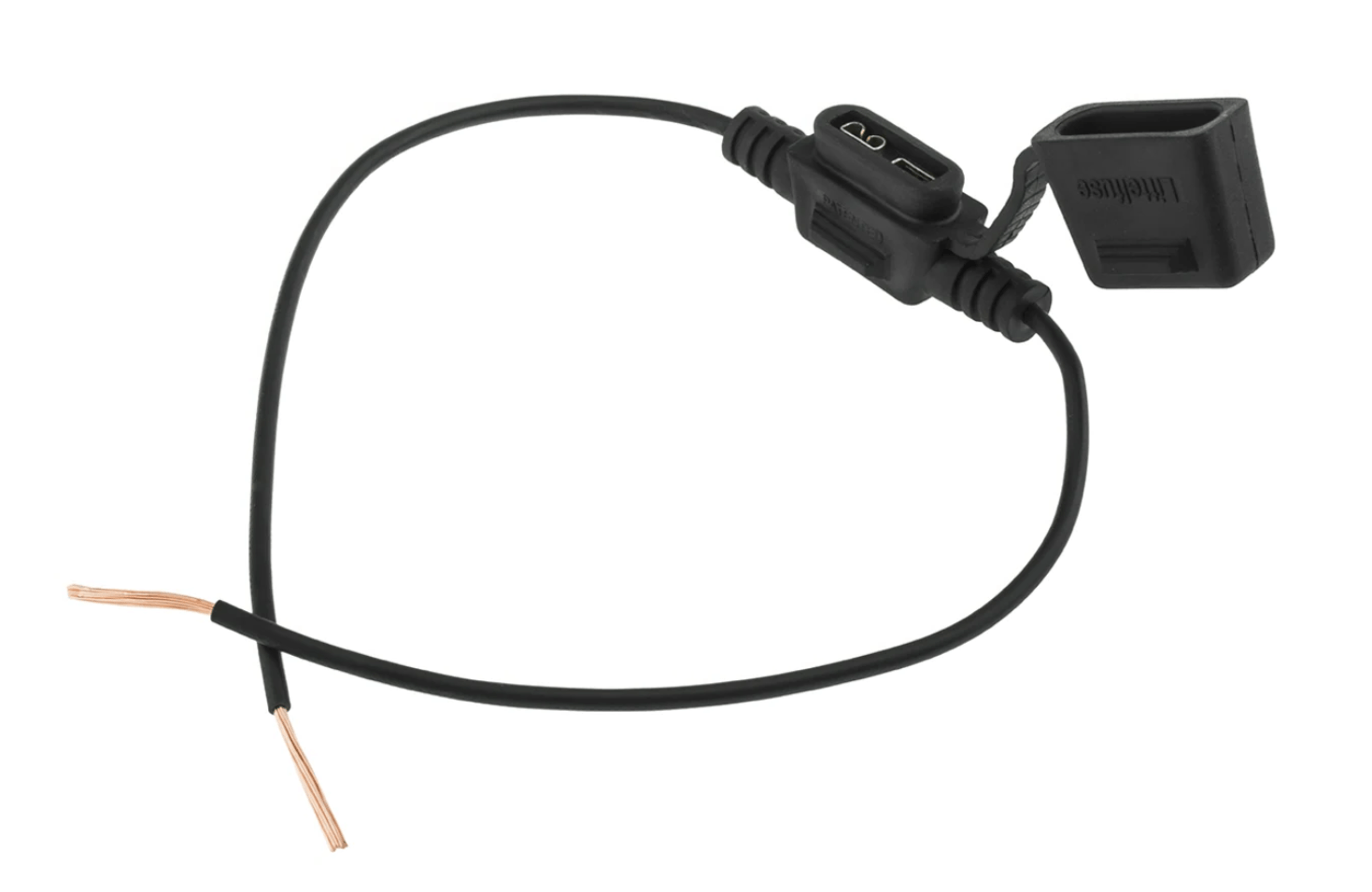
Fuses
The reg/rec is fused just like it were a battery.
The beauty of doing this is that if, for whatever reason there is an issue with the alterantor or the reg/rec, the fuse will blow instead of your lamps, or worse still your wiring melt!
I have found issues with the glass-style fuseholders in the past – the springs become weak over time, and eventually the circuit becomes intermittent.
As the fuse disconnects and reconnects to the contacts, a small amount of arcing occurs – over time a layer of ‘soot’ will build up over the contact patch, which in itself acts as an electrical insulator.
This can impact all sorts of things, not least an undesirable lighting disco effect when you ride over bumps!
I would recommend using automotive blade type fuses all round instead of the original glass type used on these bikes.
These are great, as blade fuses are available in every garage and petrol station, and are very resilient to vibration.
A 15-amp fuse in each will be fine.
Wiring Diagram
I have drawn two flavours of diagram here – the more familiar positive earth diagram.
But also, a negative earth version too – this is useful if you have other, more modern bikes in the workshop alongside your 60s brit bike and are worried about flipping between positive earth and negative earth bikes.
I have kept the wiring standard, using period correct colour codes wherever I can.
Basic Cafe Racer Wiring Diagram (Magneto) POSITIVE EARTH – PNG 3066×1841
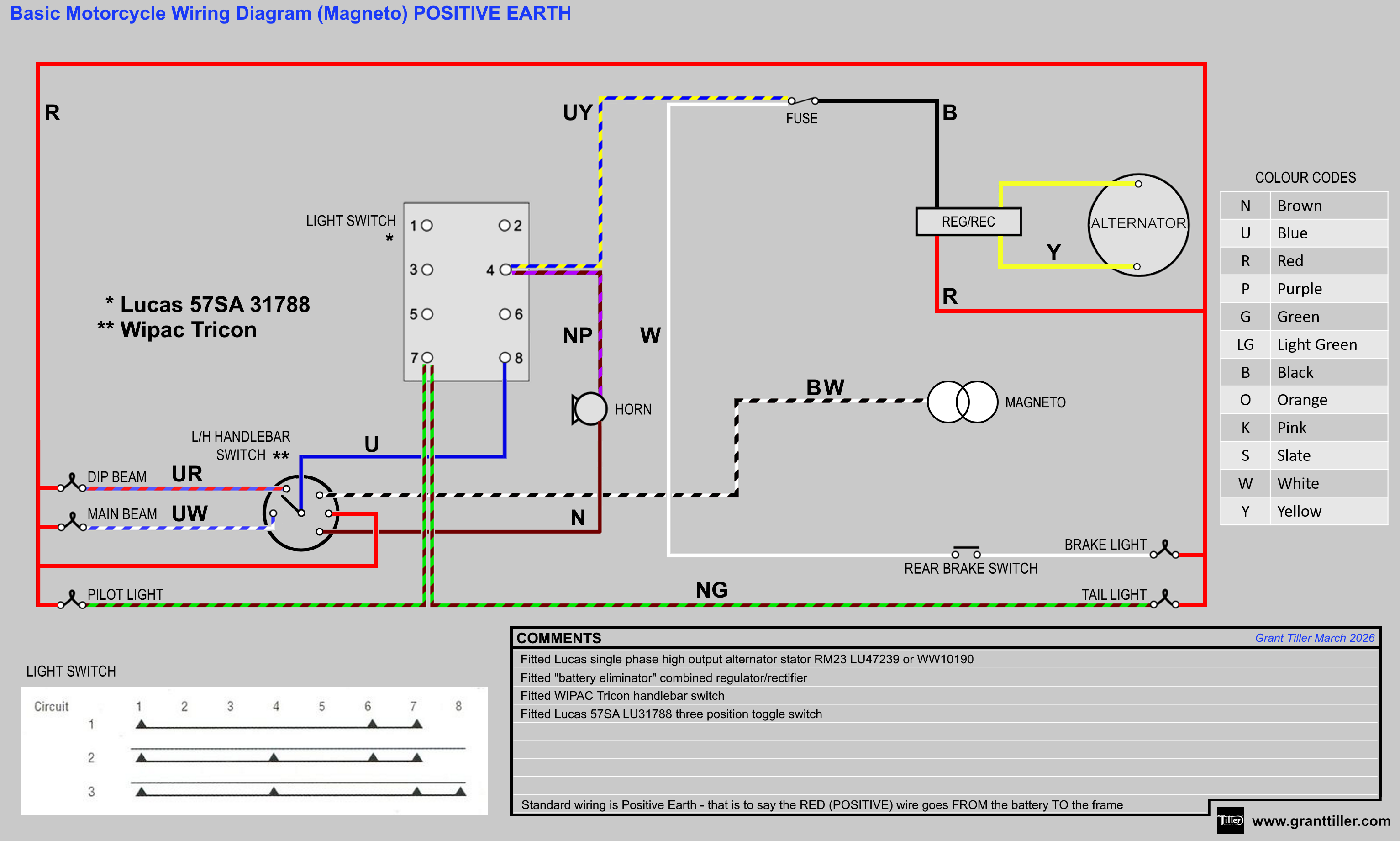
This is also available for download as a PDF
Basic Cafe Racer Wiring Diagram (Magneto) NEGATIVE EARTH – PNG 3066×1841
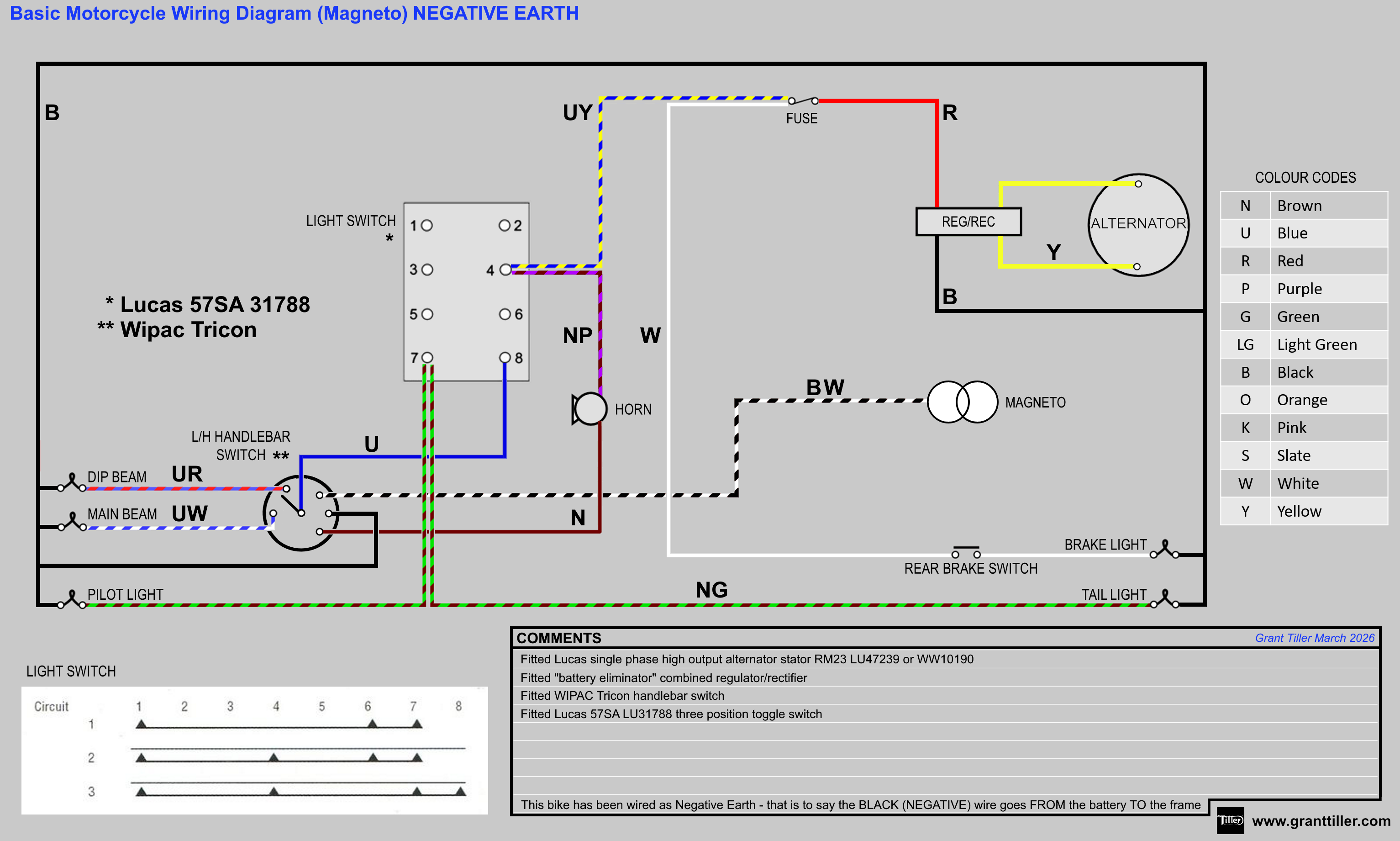
This is also available for download as a PDF
This article is from a series of three covering Simple/Basic britbike wiring diagrams:
- Simplified British Motorcycle Wiring Diagram
- Basic Cafe Racer Wiring Diagram
- Basic British Motorcycle Wiring Diagram with Electronic Ignition
As always don’t hesitate to reach out if you need any help or advice.
2 thoughts on “Basic Cafe Racer Wiring Diagram”