


I often see people asking about the zener diode in the groups and forums – what is it, how does it work, and importantly how to test it.
The zener diode is the part of the charging system that regulates the charge.
Alternator
In a permanent magnet based charging system as we have on our Commandos, (and indeed most brit bikes of the era) the Alternator produces AC.
In output terms, the faster the engine is spinning, the higher the voltage is output.

Rectifier
It is the job of the rectifier to convert this AC voltage into DC (something which can be stored in the battery, and then used to power the electronic bits on the bike)

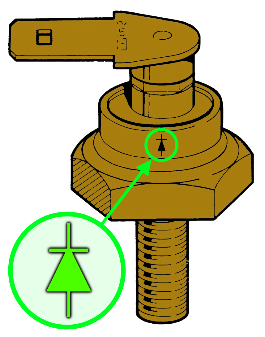
Zener Diode
It is the regulator’s (zener diode) job to keep this voltage at a manageable level – capping the amount that makes it’s way to the battery stopping it from getting boiled, and to prevent the light bulbs from popping!

You can see in the chart above, the top of the curve is flattened off – this is where any voltage over the setpoint is shed (in the form of heat, as the zener diode shorts to ground)
This is a very effective way to bring the voltage down to a manageable amount – especially on a Norton Commando, where the zener diode is mounted on the z-plate – a nice, solid, chunky lump of aluminium that is stuck out in good airflow.
It acts as a superb heatsink.
| Norton Commando Zener Diode and Z-plate | Triumph Zener Diode and Heatsink |
|---|---|
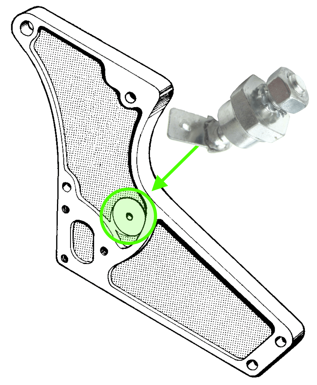 | 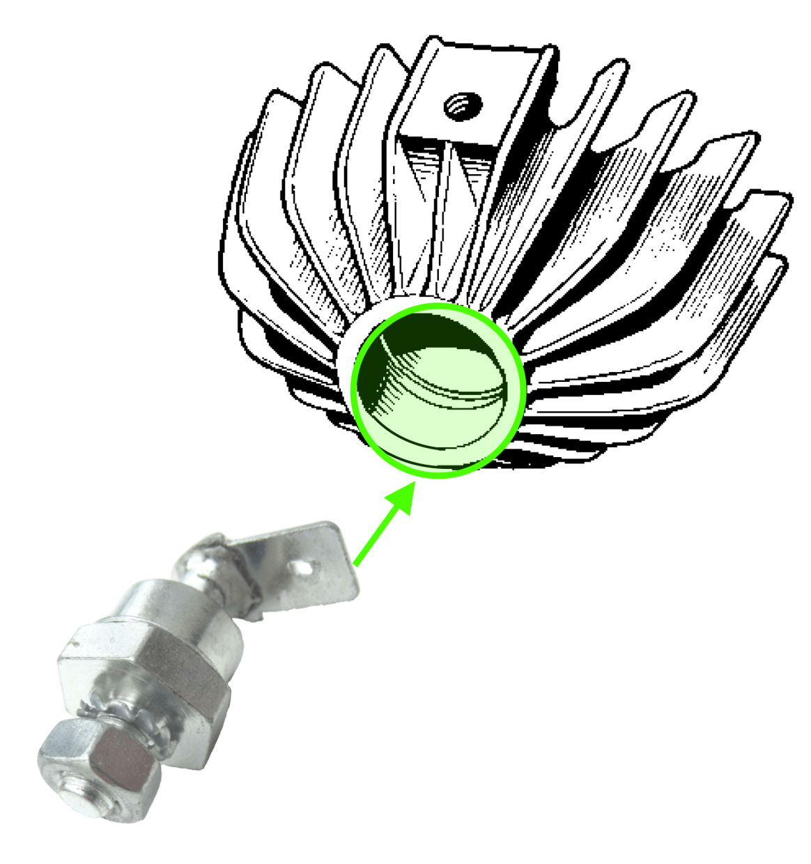 |
Back to School
In school physics lessons (or science) we were taught about diodes – some of us even got to do some experiments!
We were told that a diode should be thought of as a one-way valve, and those of us that got to play with them in the lab would have set up a simple circuit like this:
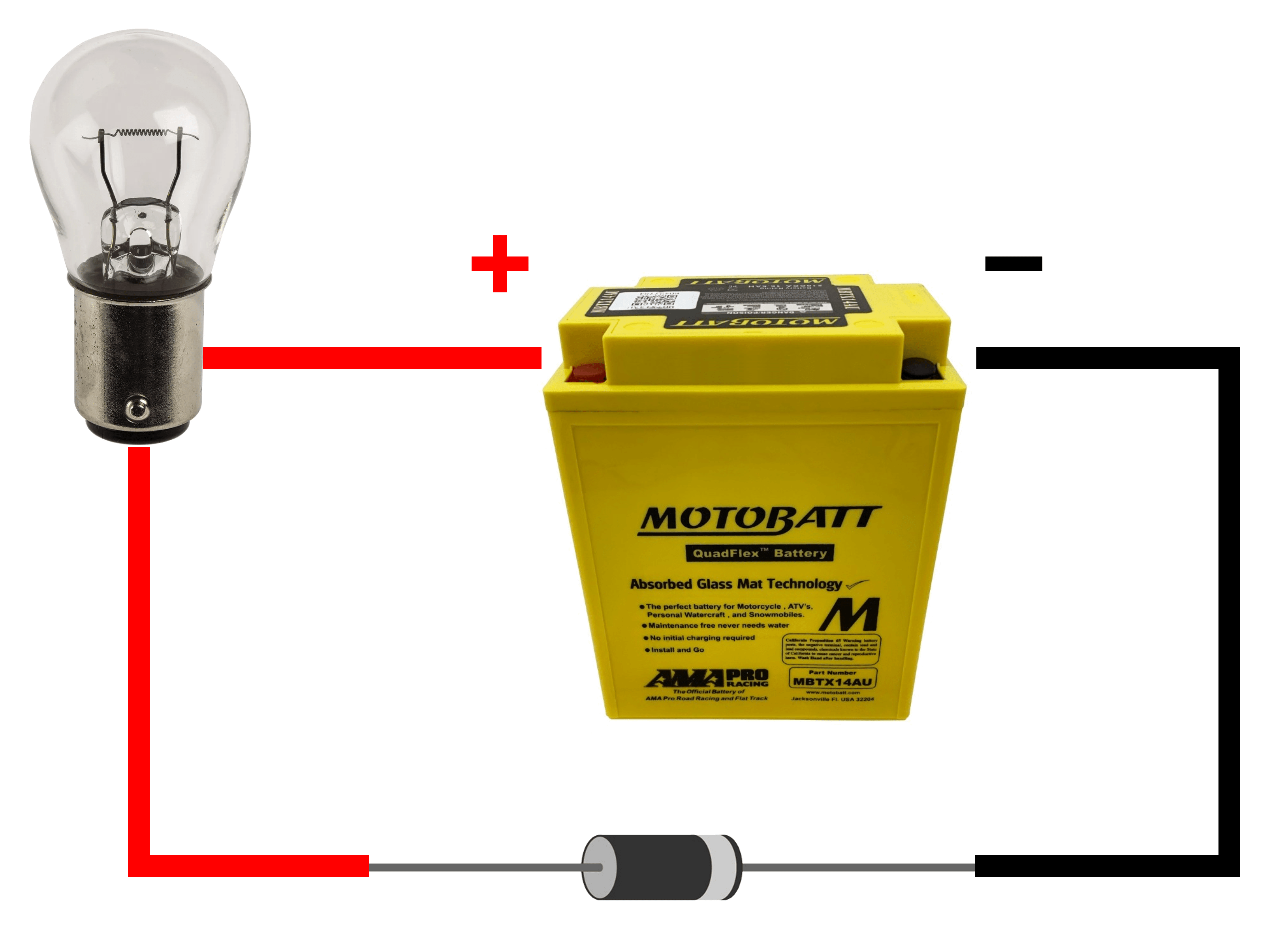
Putting the diode in the circuit this way round allowed the current to flow, and the lamp would light up.
Taking it out and turning it round the other way would stop current from flowing, and the lamp would not light.

Above you can see the symbol for a standard diode.
The arrow shows you the current flow, and the vertical line can be picked up on the component itself by a stripe on the end of it.
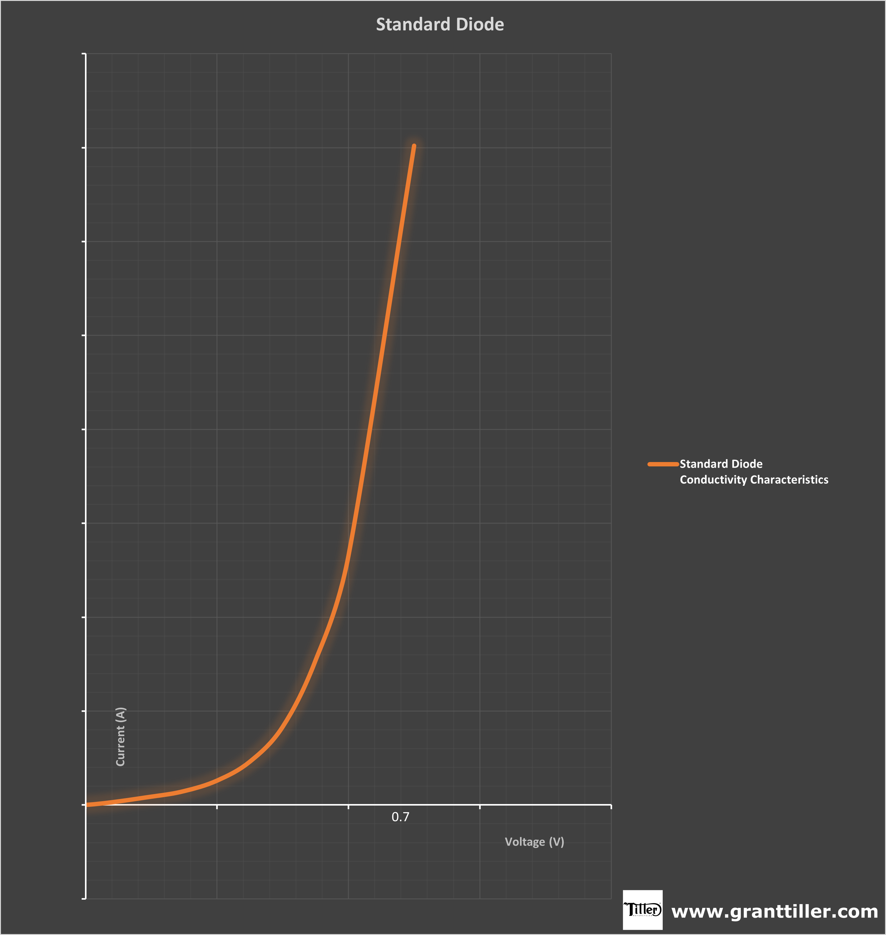
The above chart shows you how it works.
Basically, when connected to a circuit, current will start flowing when the voltage hits 0.7 volts. This is the standard voltage at which a silicon chip wakes up.
You can see that it just opens up at 0.7 volts and lets everything through – all the way up to the maximum current rating of the diode itself.
Huh? What?
All good so far right?
Easy to follow along, and bringing back memories about what we were told in school?!?
So now let me shake it all up.
Zener Diodes are completely different!!!!!
Zener
Where a zener diode is different to a standard diode is when you reverse the current flow.
Instead of working like a one way valve, it works as a pressure relief valve instead.
With the Lucas zener diodes we have on our bikes, the current will not flow, up until the point that the voltage reaches 12.75 volts, then the diode will start allowing current to flow.
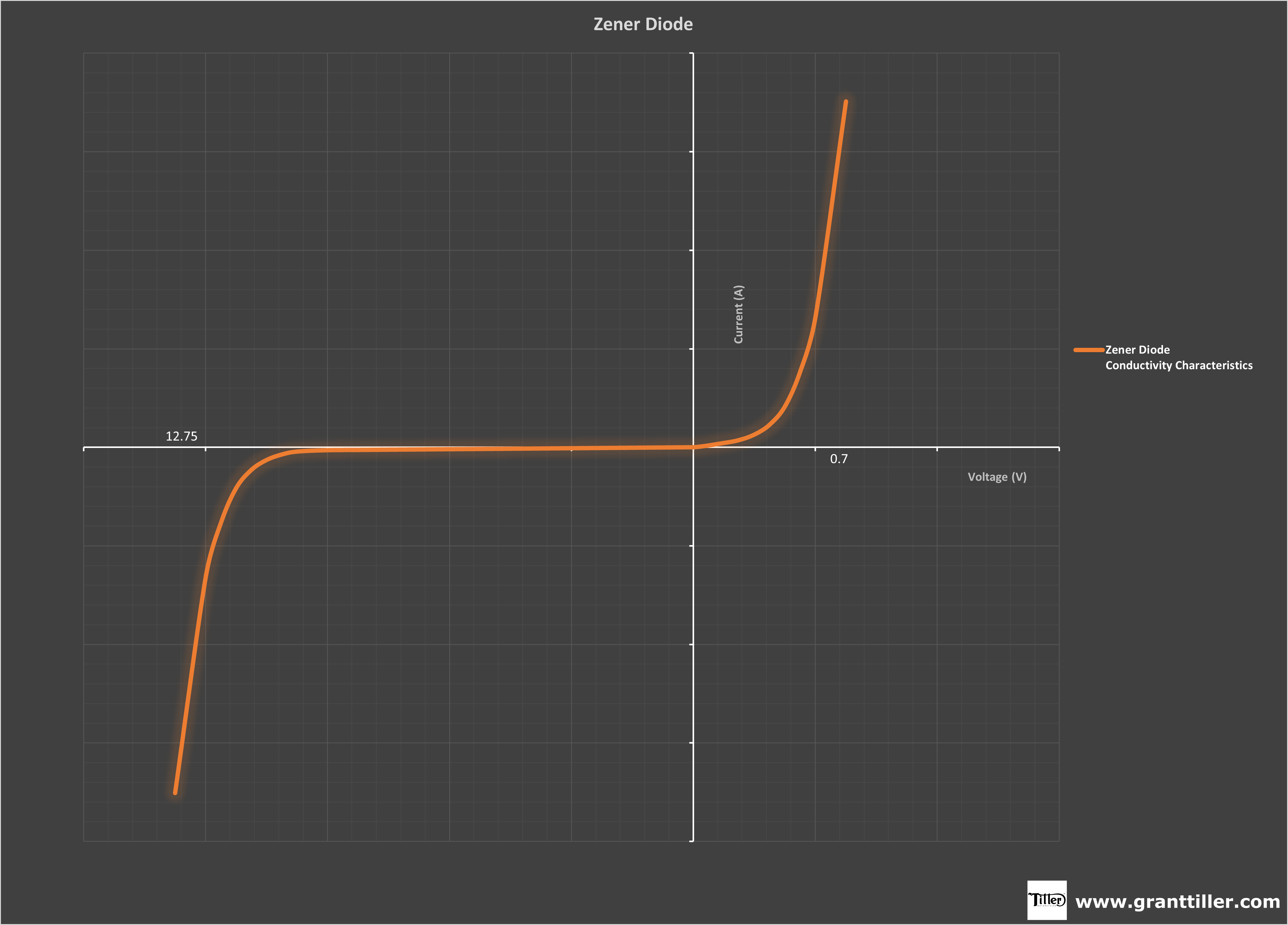
Above is how this looks in chart form.
The alternator is producing AC, the rectifier is converting it to DC, which is being used to charge the battery and power the lights and ignition on the bike.
If you are producing more than 12.75 volts (i.e., you are going fast, and the alternator rotor is spinning really quickly) then the zener diode will allow current to flow to ground.
The z-plate it’s bolted to will get hot, and the air rushing past will take the heat away.
This is a great way to handle any excess power that is produced by the alternator i.e., when the battery is charged, and doesn’t need any of the power being produced by the alternator.
The reverse voltage that the zener diode starts allowing current to flow (12.75 volts on the Lucas zener diode) is referred to as the breakdown voltage.
When current starts flowing through the device in this way, it is referred to as avalanche current.
The Lucas Zener Diodes are rated at 100 watts – so in simplistic terms, they allow just over 8 amps of current to flow through them.
The standard RM21 alternator stator fitted to our bikes from this era is classed as a 10 amp stator – so you can see that the zener diode is already running at more or less it’s capacity (if you consider the bike consumes around 2.5 amps while running with the lights off)
Balancing the power produced with the power consumed is what we are looking to achieve here.
There is absolutely no benefit at all in producing more power than you are going to consume, as once the battery is fully charged, there is nowhere to put all that excess power.
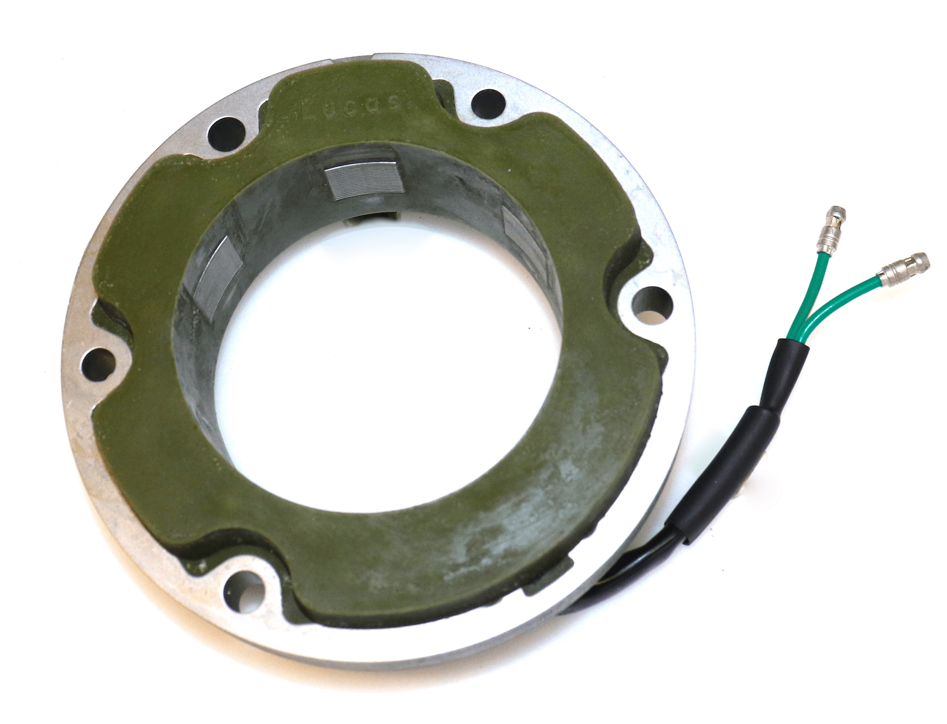
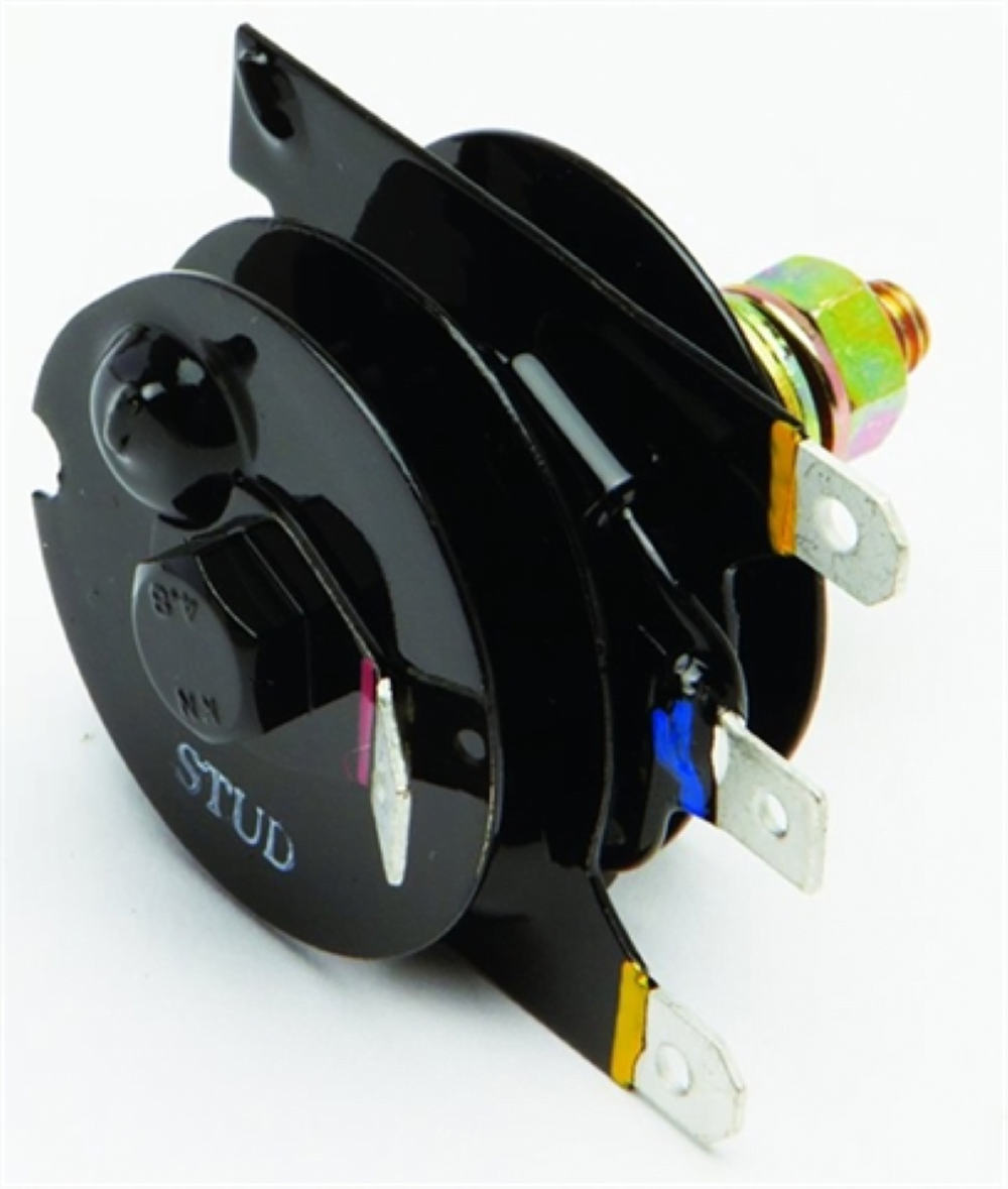
Identification
The Lucas Zener Diode was available for Positive and Negative Earth bikes.
The two are not interchangeable, as the component is both physically connected (via it’s mounting stud) to earth for the transfer of heat but also electrically connected to earth (via the same mounting stud)
In the case of the Norton Commando, you will find a red cable and ring terminal which goes over the stud, but for most other brit bikes of the era, it is simply earthed back through the frame.
Positive Earth
Lucas Part Number LU49345
Negative Earth
Lucas Part Number LU49589
I have drawn these as silver and brass coloured, but don’t use this to distinguish positive earth and negative earth components – I have seen both types in both metal finishes!
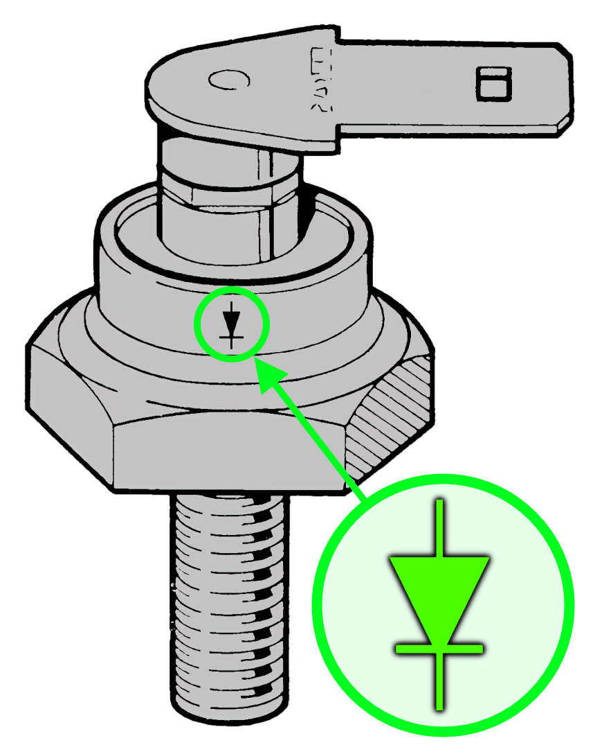
If the zener diode is in good condition, and not too scratched up, you should be able to see the diode symbol on the side of it – this will show you at a glance whether it is a positive earth or negative earth component.
If it has been rubbed or polished off, then you will need to test it to determine if it can be used on your bike.
Testing
I see many people testing zener diodes wrongly – this results in either them being identified incorrectly, or a perfectly good zener diode will be thrown away, as it appears not to work properly.
Unfortunately, the Norton Commando Factory Workshop Manual (and the same is true for most other marques) does not make it particularly clear or easy to test a zener diode.
Here are some excerpts from the Pre-MK3 and later MK3 Norton Commando Workshop Manuals that step you through testing a zener diode.
Don’t let this put you off, and read on for a better explanation, and easier way to test.
| Pre-MK3 Norton Commando Factory Workshop Manual Zener Diode Test | MK3 Norton Commando Factory Workshop Manual Zener Diode Test |
|---|---|
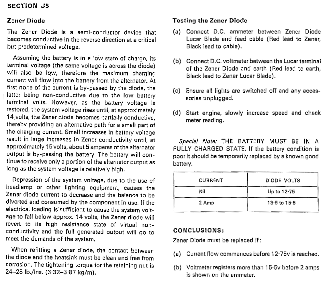 |  |
I am assuming you haven’t all got separate Ammeter, Voltmeter and Rheostats under the bench?
As I say, there is an easier way to test – which will give you a simple indication as to whether your zener diode is good or faulty.
There are two tests that we need to do:
- Forward Bias – the standard diode behaviour as we learnt at school.
- Reverse Bias – the specific behaviour of the zener diode and how it acts as a pressure relief valve.
Forward Bias
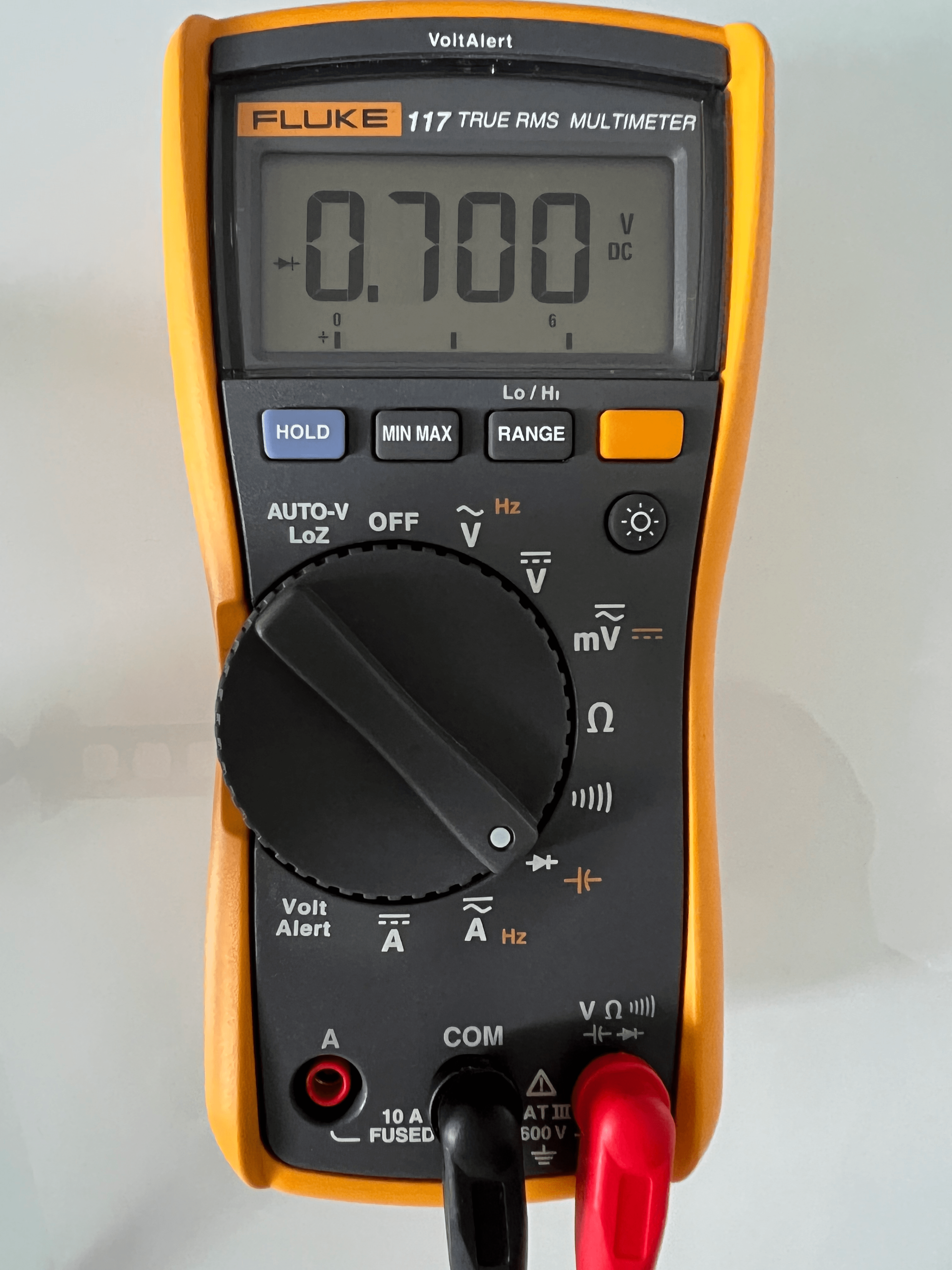
You can test the forward bias of a zener diode just like a standard diode – it will flow current in one direction only at 0.7 volts.
First make sure that your multimeter is in the correct mode for Diode testing – turn the dial to the Diode symbol, and ensure that your test leads are plugged into the correct sockets.
The Diode mode tests the voltage drop, so it is usually the DC sockets on the multimeter that you will be using.

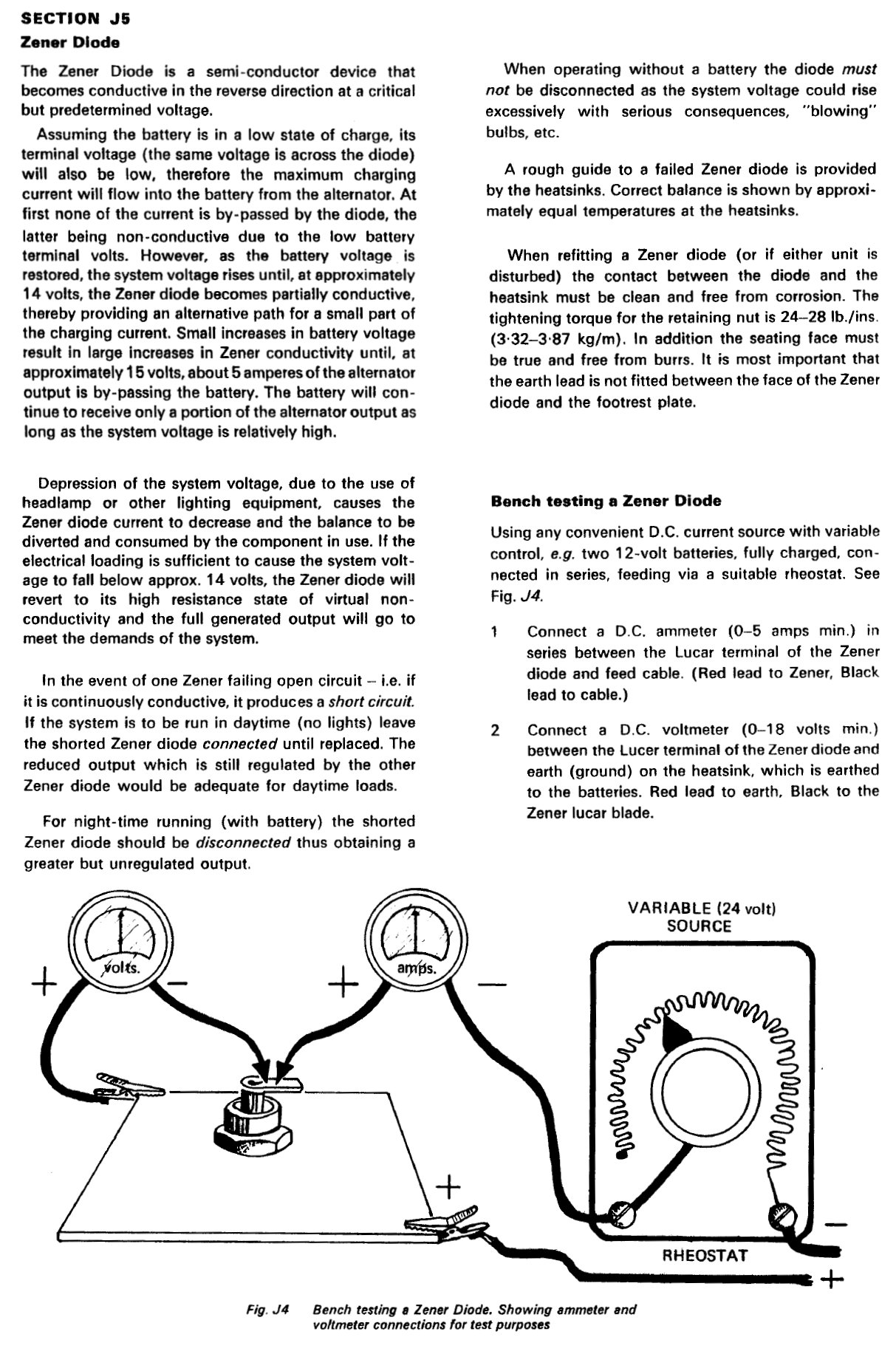
The next step is to touch your multimeter’s probes to the diode.
- Touch the red probe onto the diode’s Anode
- Touch the black probe onto the diode’s Cathode
The following pics show you which side is which:
| Standard Diode | Positive Earth Zener Diode | Negative Earth Zener Diode |
|---|---|---|
 | 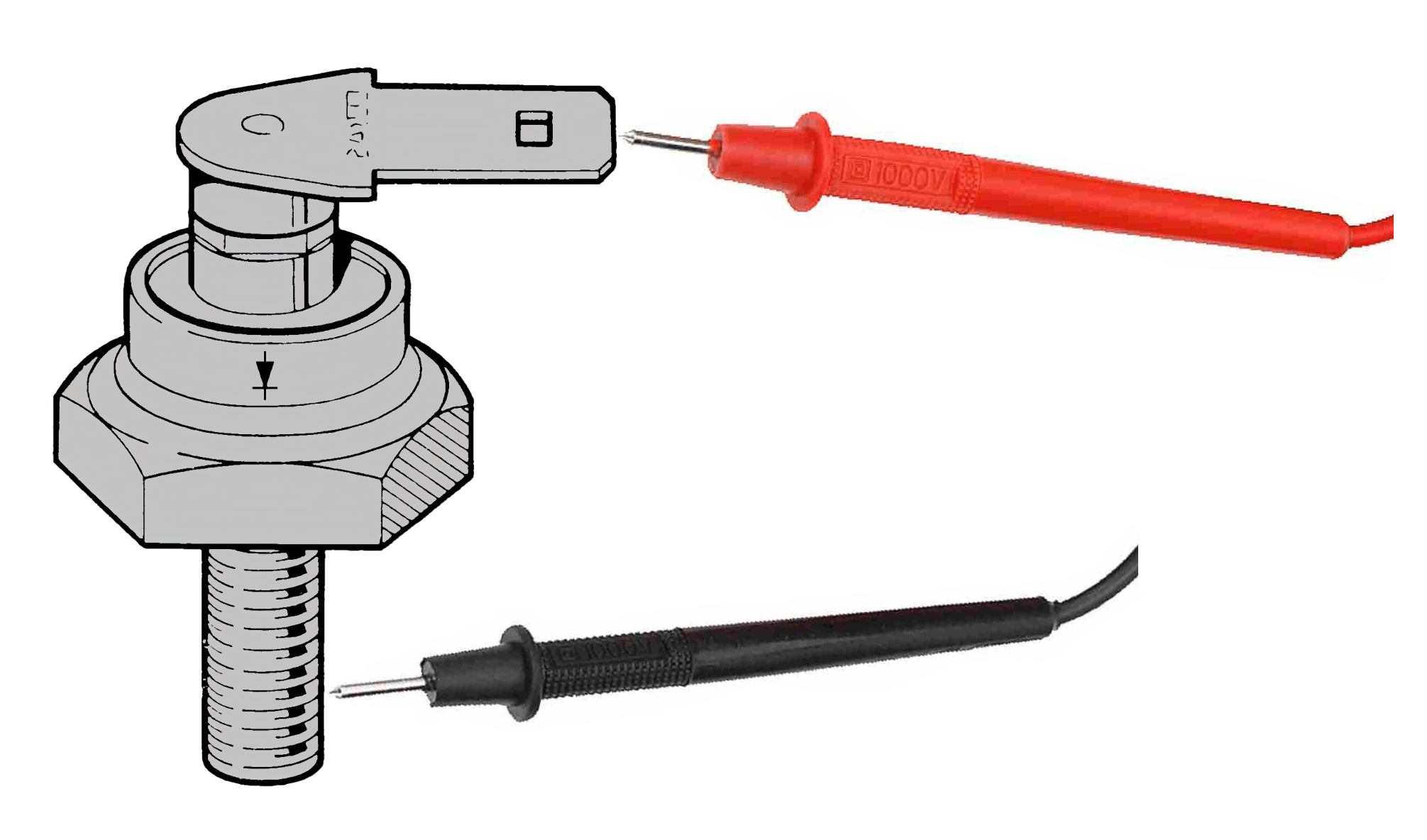 | 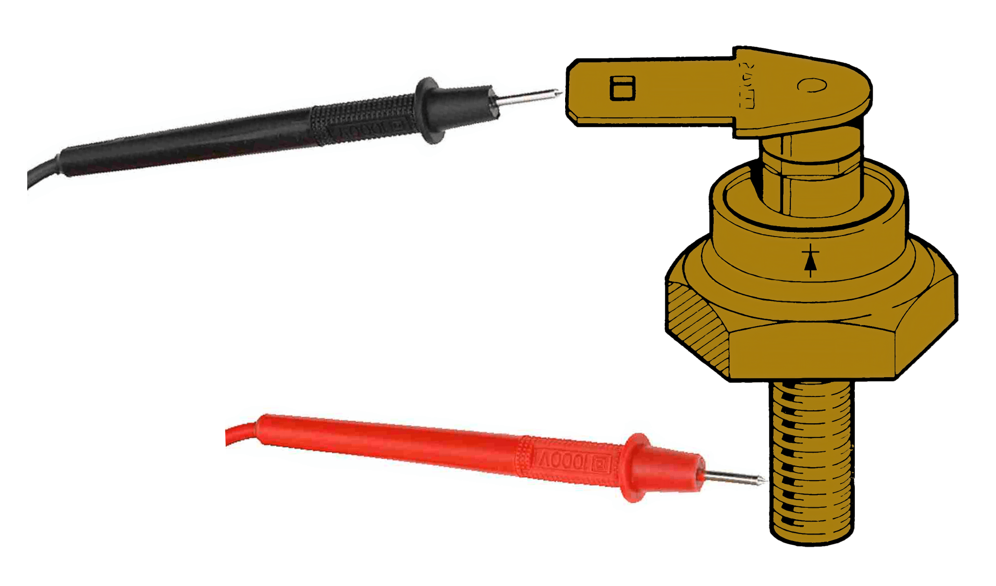 |
What we are testing here is the voltage drop across the diode.
For example, if you pass nine volts through the component, how much voltage does the component consume.
As I said previously, in the case of our diode – assuming it is fully functioning, we would expect to see 0.7 volts – the voltage at which a silicon chip gets excited.
In reality, anything between 0.5 and 0.8 volts would indicate that the diode is good and healthy – (I usually see between 0.55 and 0.62 on a healthy Lucas LU49345)
- If the multimeter shows OL, it is suggesting that the diode is not working (i.e., that current is not flowing through it at all)
- Similarly if the diode is showing less than 0.4 volts, it is suggesting that the diode is shorted and therefore faulty.
Reverse Bias
The reverse bias of an automotive zener diode is a little more awkward to test.
This is because the breakdown voltage is 12.75 volts, but typically most home-use multimeters run off a small PP3 9 volt battery.
That means you will not be able to test the reverse bias behaviour, as you will never reach the 12.75 volt breakdown voltage that is required for the zener diode to fully breakdown and flow avalanche current.
Instead, the best way to test this is by using a freshly charged bike or car battery (or better still a bench power supply where you can turn up and down the voltage)
Let’s assume you have a freshly charged bike battery.
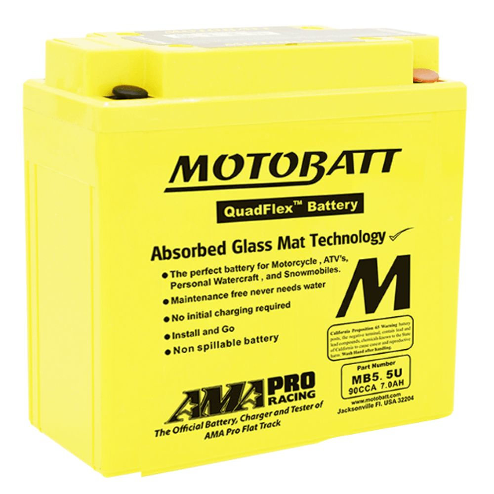
Lead acid batteries (including gel, AGM, flooded and drycell) are 2.1 volts per cell, so you will typically see 12.6 volts at rest.
However, when a battery is fresh off it’s charger you will see the charge voltage to be between 13 and 14 volts. (it will settle back to it’s rest voltage of 12.6 volts over a few hours)
Put your multimeter across the battery terminals, and check that it is between 13 and 14 volts.
Assuming it is, now is the perfect time for you to test the zener diode’s reverse bias characteristics.
Simply go ahead and connect your zener diode and a filament lamp to your freshly charged battery (I like to use a 21 watt lamp from a turn signal, but a headlamp will also do if you have a spare one)
| Positive Earth Zener Diode | Negative Earth Zener Diode |
|---|---|
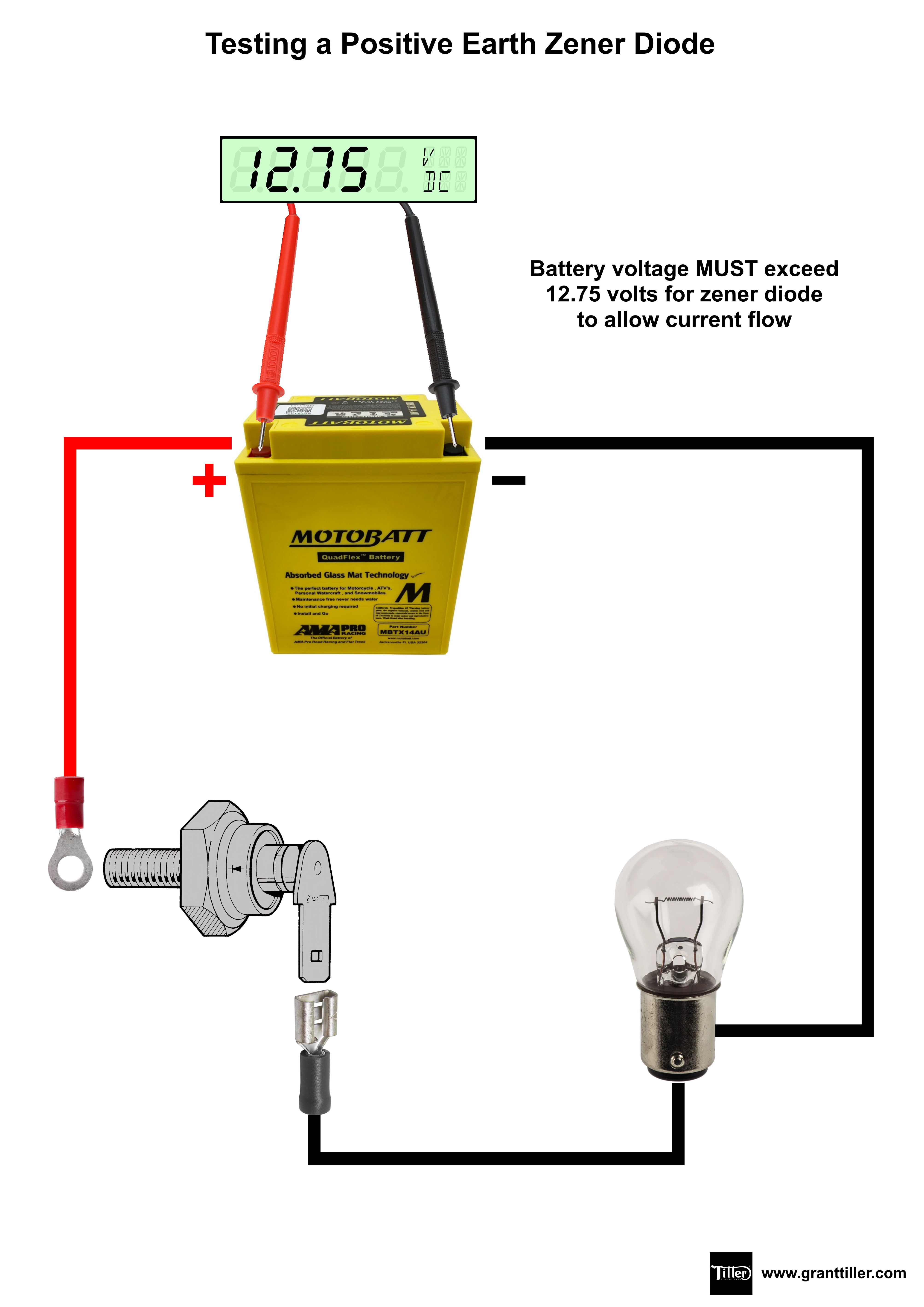 | 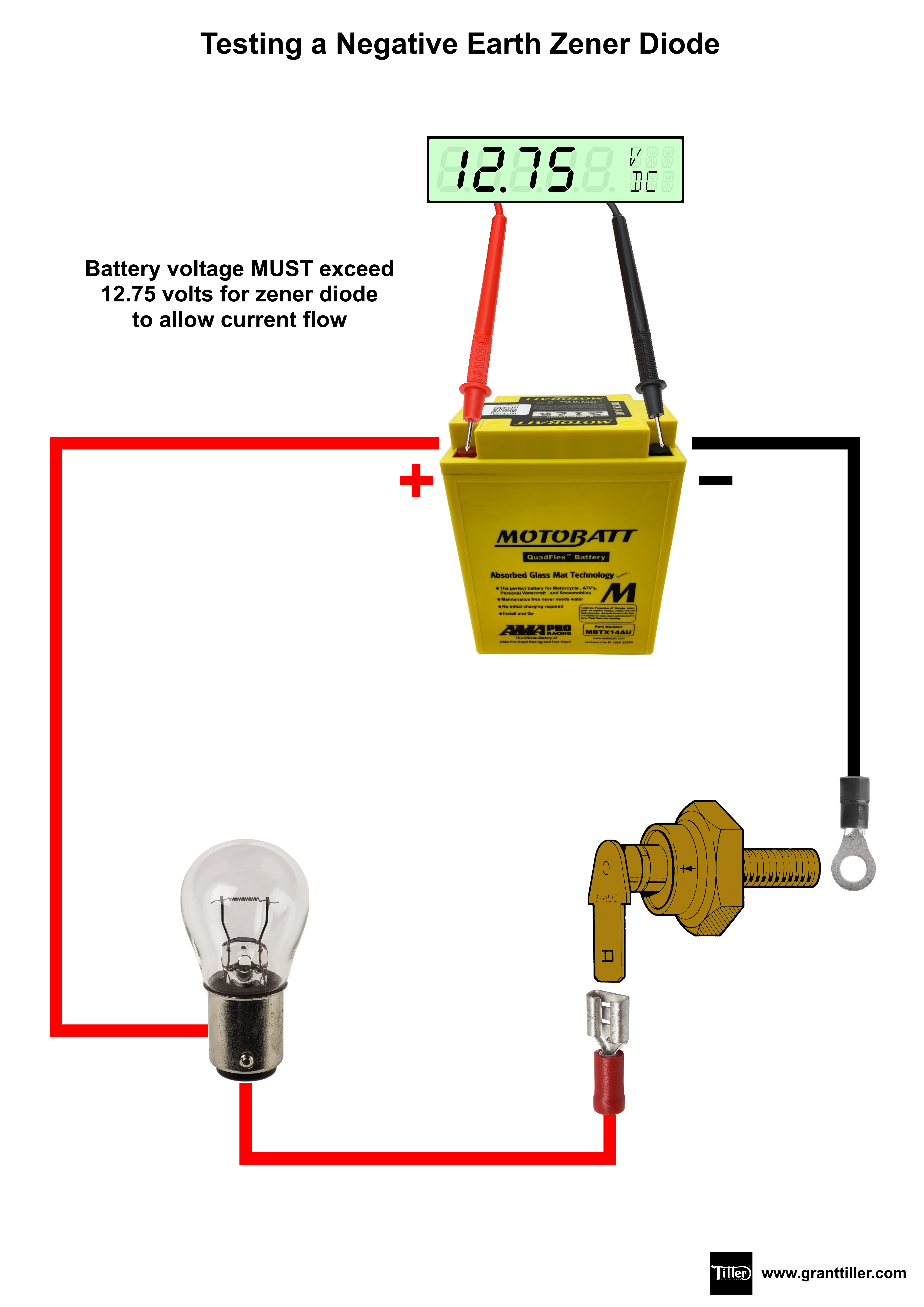 |
| A handy sheet of how to test a Positive Earth Zener Diode is available for you to download and print out here. | A handy sheet of how to test a Negative Earth Zener Diode is available for you to download and print out here. |
With the lamp connected as shown in the diagram above, you should see the lamp light up, as the breakdown voltage is lower than the battery voltage, so avalanche current will be allowed to flow.
Very quickly though (around a minute for a 21 watt turn signal lamp, but even quicker for a headlamp) you will see the light go out.
This is because the voltage of the battery has now dipped under the breakdown of the voltage of the zener diode.
If you put your multimeter across the terminals of your battery after this test, you should see that it’s voltage is now under 12.75 volts.
Conclusion
Zener Diodes are tough and resilient little things, that seldom go wrong.
Usually the issues with a charging system are down to the rectifier, where the soldered diodes between the wafer cooling fins shake themselves apart with the vibration of the bike.
If a zener diode is not working on the bike, nine times out of ten I have found it is down to a bad cable connection, or a poor grounding to earth.
It is important to keep the zener diode clean and ensure both connections are good. It has been on your bike for fifty or more years already, and there is absolutely no reason why it won’t last another fifty years!
Diodes have not changed, so there is no technical advantage in swapping out to a reg/rec (in fact there are several disadvantages as I have covered in other articles)
The simple tests shown above will prove to you whether your zener diode is working or not.
While I understand the factory manual showing us a technique with a rheostat so that we can see exactly what the breakdown voltage is before avalanche current flows, in reality this is more information than we need.
With a zener diode, it is not serviceable or adjustable – either it works and it can be put back on the bike, or it doesn’t work, and must be thrown away.
If you have diagnosed your zener diode and found it to be faulty, please do the world a favour and throw it away!
I have run into many instances where a zener diode has been taken off a bike and put under the bench – only to be resurrected at a later date or by someone else. It was often thrown under the bench because it stopped working!
The other thing I have found is several zener diodes put on eBay that have later turned out to be faulty.
…that’s not good sport!
Hierbij volgende vraag:
BSA 650 T 1971
Tussen de min van de accu en de zenerdiode zit een zekering (max 35 A)
Bij het starten van de motor gaat na een minuut deze zekering steeds stuk.
Ik kan de oorzaak maar niet vinden.
Zijn de diode en/of gelijkrichter kapot? (diode heeft + aarding)
Graag antwoord.
Mvg, Frans
TRANSLATED FROM DUTCH
Here’s the following question:
BSA 650T 1971
Between the negative of the battery and the zener diode is a fuse (max 35 A)
When starting the engine, this fuse keeps blowing after a minute.
I just can’t find the cause.
Are the diode and/or rectifier broken? (diode has + ground)
Please respond.
Regards, Frans
Hi Frans,
I assume your ignition switch is off, and the fuse is blowing as soon as you replace it?
If that is the case, the issue is either with your zener diode, or with your rectifier.
The rectifier is the most common fault, as the soldered joints between the cooling fins shake apart with vibration, which can short out to ground (that will blow your fuse)
Try disconnecting the NU (brown/blue) cable that goes to your rectifier, then replace the fuse again.
This will tell you if the issue is the rectifier.
If the fuse still blows, then you know for sure that your zener diode is the fault.
Cheers,
Grant
Hey, great article, I enjoyed reading it – some very good information. I have a question: My 1969 BSA A65 has some sort of aftermarket LED that changes lights when the charge is low, and goes green when ever it is ok. I only have the bike for a few days, so I took it out and after a few KM riding with somewhat higher revs the warning light started to blink red like crazy, so it seems to me it is over charging, at least that’s what I suspect. It only comes on after a period, so I can’t test it. My question is, do Zener diodes have this problem, ist it common? Any odea how to test it? Thanks 🙂
The charge warning lights are good – they give you more information about the charging on the bike,, plus the state of the battery.
One important thing you need to check with your zener diode is that it is clean.
A good connection with the bike is important for heat transfer, and electrical earth.
…unfortunately, they get corroded pretty fast, and that is usually the issue.
The other thing to check is the connectors on the cable going to it – the vibration on the bike can cause the bullet connector to become unreliable.
The zener diode itself is pretty robust – and I don’t often see them fasil.
To be honest, I find them far more reliable than the modern aftermarket reg/recs that people fit!!!
If I replace my auto advance unit (
AAU) and points, would you (could you) still run the rectifier and zener diode? Six volt coils will be used if it goes electronic ignition.
Hi Roderick,
Yes, absolutely!
Think of the charging circuit as a completely different system to the ignition (either standard points or electronic) – there is no interconnection between the two.
…which means you can keep your rectifier and zener with no problem at all!
Hi
Is there a 6 volt version available?
Unfortunately, they never did a 6 volt zener diode for automotive applications that could comfortably handle the wattage requirements.
It means you are stuck with the modern reg/rec, which is the only readily available alternative for 6 volt machines.
Norton mk3. Is it likely a loose zener connection on one one side has caused the other zener to overload and fail? It tests as short circuit both ways. I’ve tracked down the last zener in captivity, so I’d hate to be wrong! Everything else seems OK, but charging is close to zero. Ta. Nigel
Hi Nigel,
Provided you keep the zeners clean and corrosion free, they are amazingly robust little devices, and prove to be one of the best bits of the electrical system in terms of standing up to the test of time.
What normally happens on a MK3 is failure on the half-wave rectifier – the diodes soldered between the cooling “wafer” fins shake themselves loose (there is a limit to what the isolastics can do) which results in failure.
These soldered joints tend to go one at a time, and with half out of action, you find that too much power gets put through one of the zeners resulting in burnout.