

Bill Horribine reached out through the website for some guidance on rewiring his 1971 Norton Commando Long Range Fastback.
Bill has chosen to modify a standard wiring harness – hopefully the help and guidance here will assist him (and others) who may be doing something similar.
Battery Connection
As you read through this article, and start to look at the diagrams, be sure to notice that there is only one connection to the battery positive – this is the heavy 6-gauge cable that goes to the primary case for the Colorado Norton Works Electric start.
It is important not to take any other connection to the battery on this side, as if for any reason you have disconnected the heavy gauge cable (maybe you are doing some maintenance work on the primary), and you inadvertently touch the starter button, you can quite easily pull 200 amps of unfused power through the other cables in the wiring harness that are rated at 20 amps.
The wires simply melt!
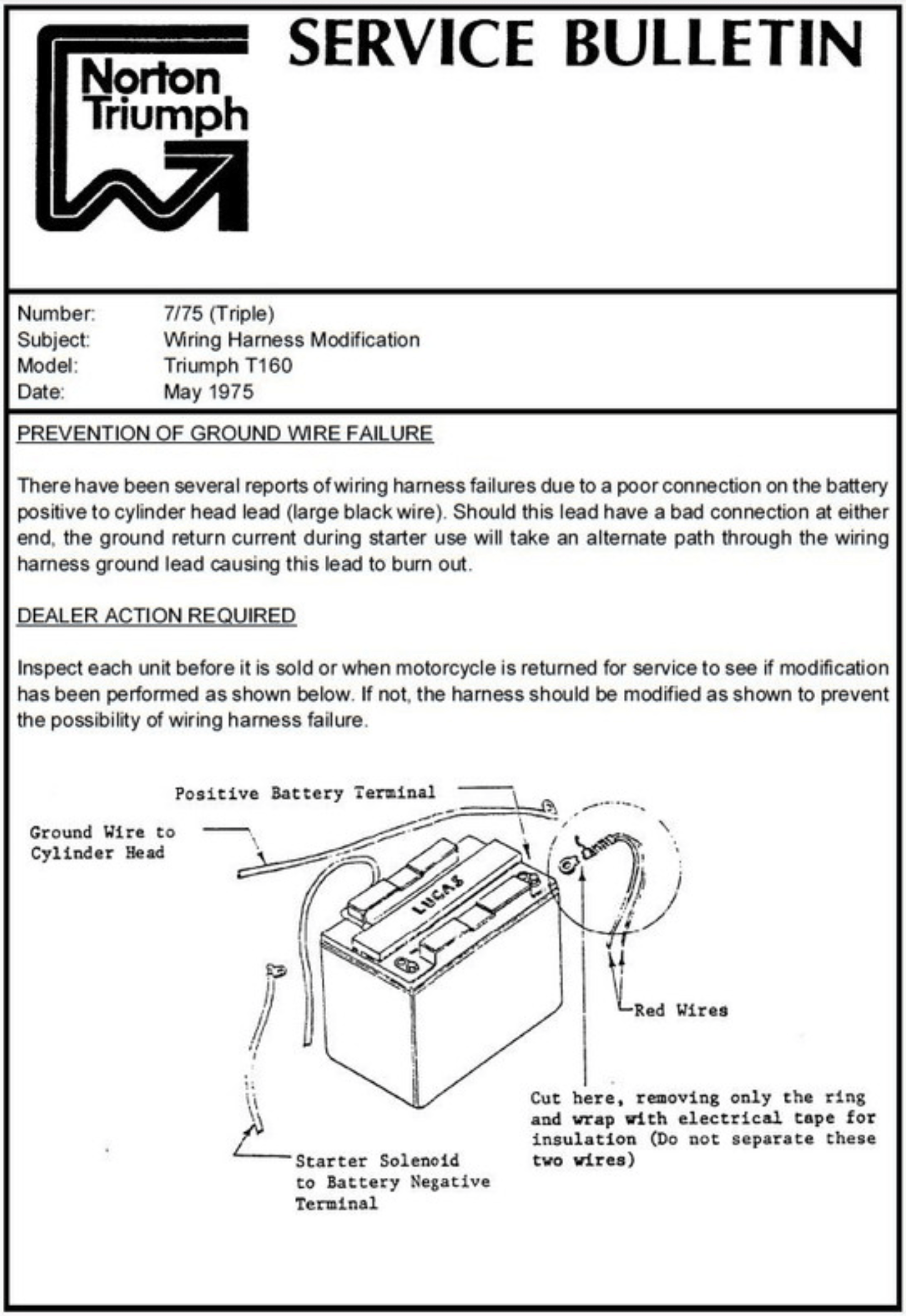
NVT had the same problem with the Triumph T160 back in the day.
They sent a Service Bulletin out to the dealers and distributors instructing them to cut the light gauge wire from the battery, leaving only the heavy one. The same thing should be done on the MK3 Commando too (there are a lot of commonalities with the electrical system on the MK3 Commando and the T160 Triumph, as they were under the same ownership by that point)
All of the MK3 diagrams here on my site have that cable deleted for this very reason.
You often see MK3’s with this cable cut. I think it is common for a new owner of a bike to wrongly reinstate this wire when they open the side cover for the first time and discover that the wire has been cut. Wrong – it’s been cut for a very good reason!!!
Electronic Ignition
The new kid on the block for Electronic Ignitions is Tri-Spark.
Well, I say new kid – they have been around since about 2009.
You can find the Tri-Spark website here.

Tri-Spark get a bad press for reasons I have gone into in an article here – I have never, ever had an issue with them – always reliable, great customer service, and fully of some great features.
They are my personal preference for electronic ignitions, and I recommend them to anyone thinking of moving based on my own great experience.
The Tri-Spark unit is a one box solution – all the gubbins are mounted inside the points cover – no additional black box to try and hide under the tank, and very, very simple to connect up.
The wiring is as follows:
| Wire Colour | Description |
|---|---|
| Red | this is the positive feed to the Tri-Spark unit. Most people attach this wire to one of the two fixing posts inside the points cover. I would personally recommend running an additional wire up to the coils, I always draw my wiring diagrams in this way to cover this recommendation |
| Black/Yellow | this is the negative feed to the Tri-Spark unit. This joins in to the White/Yellow that is the kill switch on your handlebar switch cluster |
| Black/White | this is the negative supply FROM the Tri-Spark TO the coils |
You’ll note in the wiring diagram below that the Ballast Resistor and Condensers have been removed as part of the conversion to Electronic Ignition.
Bill has a dual output single tower coil – so there is no worry with moving the pair of single 6-volt coils to a series setup for wasted spark ignition as with a normal points conversion.
You’ll note in the wiring diagram below that the Ballast Resistor and Condensers have been removed as part of the conversion to Electronic Ignition – they are no longer required.
Two major benefits of the Tri-Spark:
- a very low operating voltage – as low as 8 volts means your bike will still run with a less than optimal battery and charging system
- circuitry performs the electronic equivalent of advance and retard to make the bike easier to start and stop the possibility of kick-back. This makes it gentler on your knees, and kinder to electric start systems (aka sprag clutches and in the case of the Alton electric start kit tiny plastic shear pins)
Alternator

Bill has very sensibly opted for a three phase alternator stator.
This is, in my opinion, a great option to go for and is far superior to the factory original single phase unit.
The spec is as follows:
- Lucas RM24
- 3 Phase
- 14.5 amp
- Part Number LU47244
- Also found under Part Number WW10192L
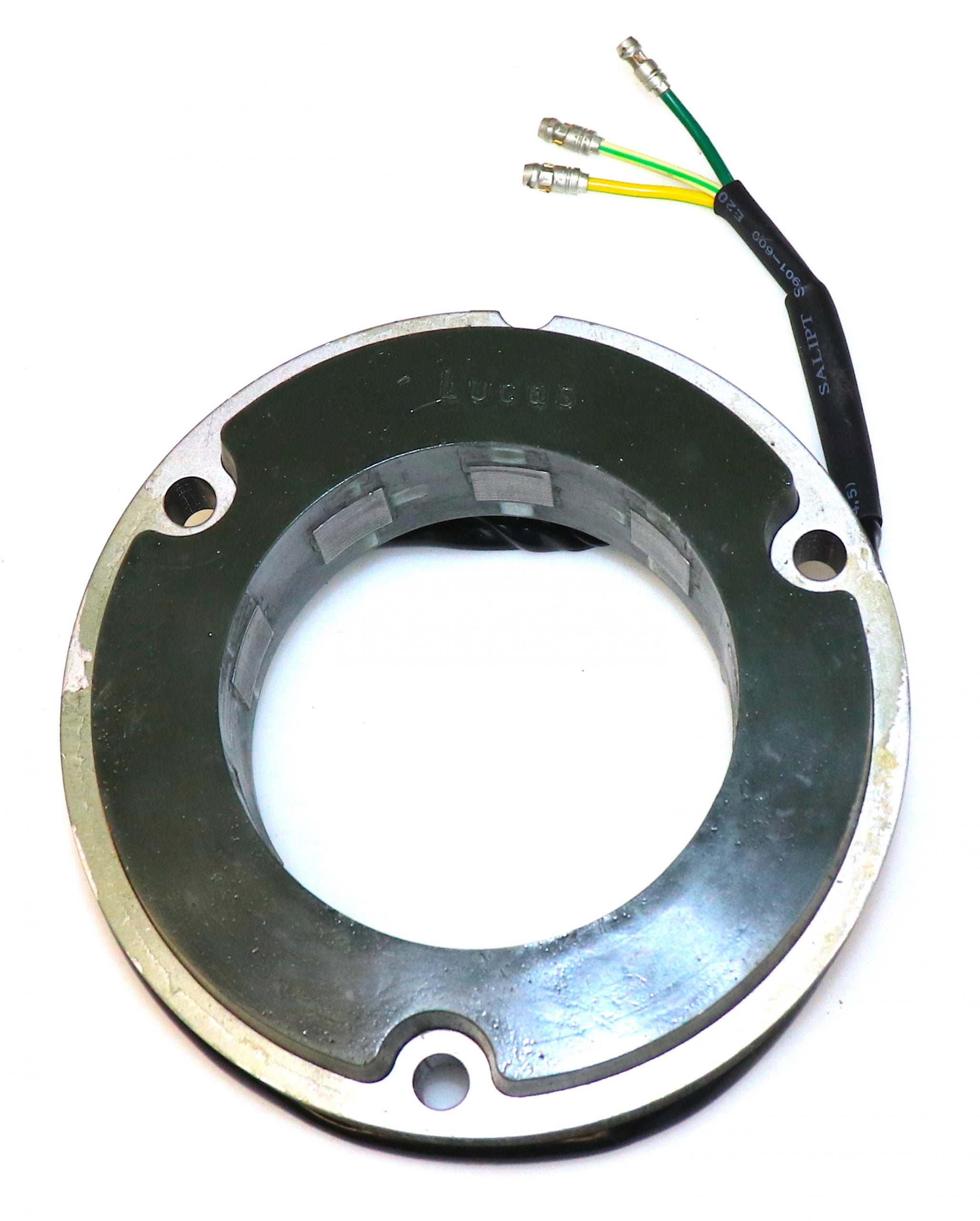
This stator is the high output version, putting out around 14.5 amps – this is a sound choice on an electric start bike, as the duration of most rides will be spent recharging a depleted battery.
In addition, because it is a three-phase unit, output is produced at a much lower RPM making this an ideal solution for around town and in stop start traffic conditions.
As always, I recommend that you ride with your headlight on, as this will always help with the longevity of the components that make up your charging system.
Regulator/Rectifier
Another of the most common upgrades or modifications for a classic british bike is to add a combined regulator/rectifier unit.
Our Commandos use a blue can capacitor, zener diode (which can be found mounted on the back of the z-plate) and rectifier unit.
A combined regulator/rectifier replaces all of these components with one package.
Bill has gone for the relatively new to market Tri-Spark MOSFET unit.
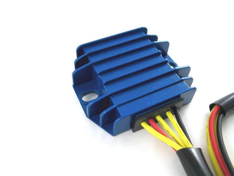
It is certainly easy to spot in it’s blue anodised heatsink!
There are five wires to connect:
| Wire Colour | Description |
|---|---|
| Yellow (x 3) | these are the AC input and pick up on the three wires coming out of the three phase alternator stator (connection can be any way round, as this is the AC side of the circuit) |
| Red | this is the Positive output and will join to one of the red wires in the harness |
| Black | this is the Negative output (known as the hot wire) – I recommend that it is wired directly to the battery negative terminal via it’s own dedicated fuse. |
The spec on paper is very good, being able to handle up to 20 amps.
And the benefit of MOSFET is much more precise control of the charge voltage. I have done a deep dive into reg/rec types and behavior which you can find here
Here are the wiring instructions for the Tri-Spark VR-0030 MOSFET regulator/rectifier.

The other piece of great news is that our friends over at Andover Norton are carrying this unit in their inventory!
Their part number is 13.1801 and you can find it here:

It is also now available from RGM and Rex’s Speedshop – my other two favorite suppliers!
Warning Light Assimilator
The Lucas 3AW 3 wire ‘silver can’ assimilator is the most unreliable part of the bike in my opinion.
Think of the old-fashioned mechanical bi-metallic strip that is part of the thermostat on an old central- heating system – it’s basically the same sort of technology used here. Warming up and expansion/contraction of different metals to open and close contacts.
Couple that to a rattly, vibrating motorcycle, and you can suddenly understand why they were not wholly reliable.
Plus, there is the matter of what they are actually doing, and how much use that is.
The 3AW is looking for about 6 ½ volts coming out of the alternator stator.
It gives you no information about the charging (i.e., the regulator (zener) and rectifier)
It gives you no information about the state of the battery.
Charge Warning Light

Tri-Spark is one of the manufacturers that has detailed that the factory warning light assimilator is NOT supported with their reg/rec unit.
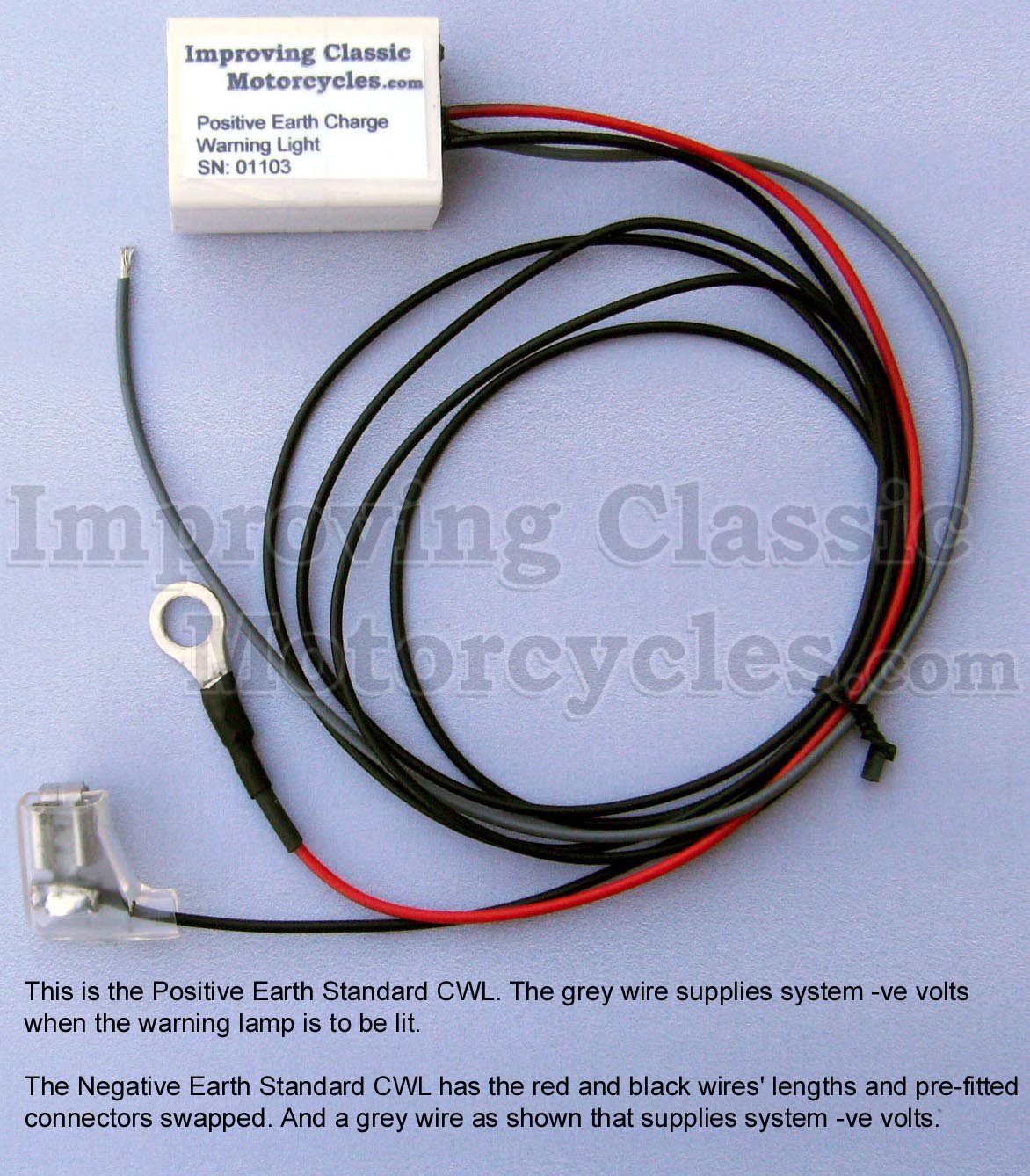
I can certainly recommend the Improving Classic Motorcycles charge warning light as a brilliant alternative.
I use them myself, and have had a good experience with them.
The nice thing about the Improving Classic Motorcycles unit is that you can retain the original warning light – so it looks totally factory (this for me is an important factory with the MK3 with it’s quirky little instrument panel).
It gives you a lot more useful information about the state of the battery and charging system compared to the standard assimilator unit, which looks for AC output from the alternator stator only.
Flashers
Bill will be using LEDs for his turn signals and warning lights, so it is important to change the factory original flasher unit for a solid state one that can handler lower current lamps.
I have written about upgrading turn signal flashers to a more modern type that will allow for LED lamps in the future, or different wattage bulbs without effecting flashing speed. You can find the article here.
There are several options available for flasher units, but I recommend Classic Car LEDs as one worthy of consideration.

They have a solid-state unit available, and the option of Positive Earth – so perfect for our bikes.
The reason I like these units is that the same unit will support incandescent lamps or LEDs, so there is a good degree of future proofing.
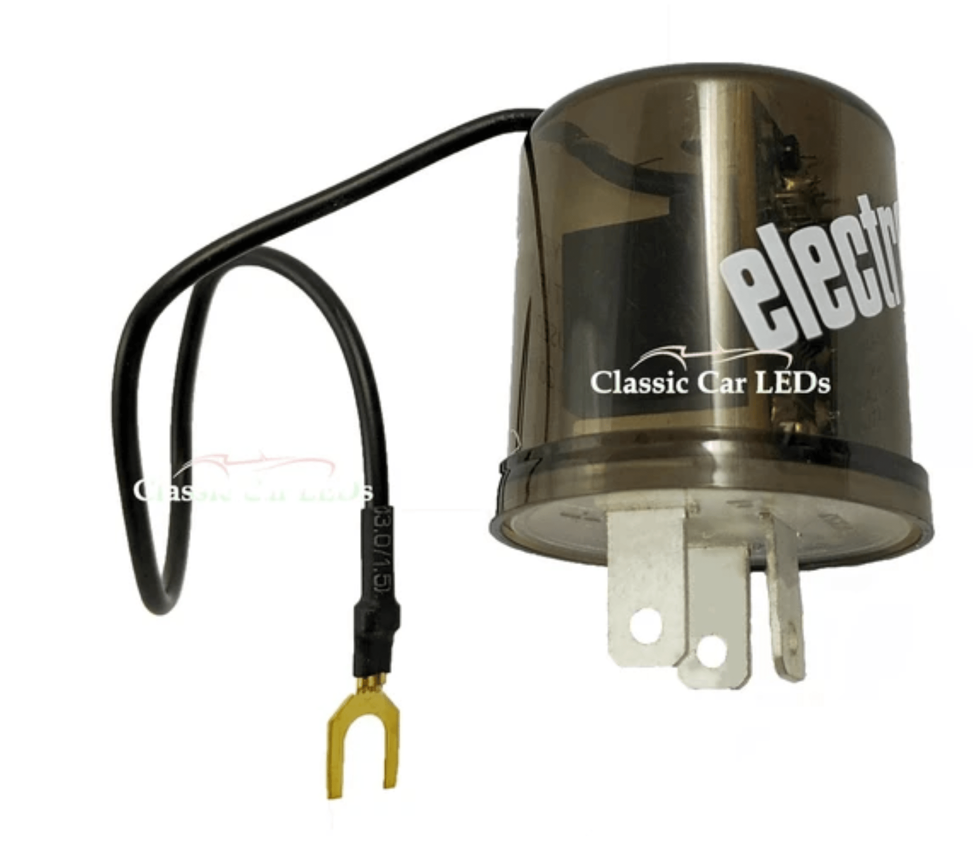
The unit is a simple canister design, and can easily be hidden away on the bike.
Here follows a copy of the wiring diagram as per their website:

You will note that this has a separate line to the warning lamp, which means no requirement for additional diodes (or tweakers).
For the sake of running one extra wire, it’s a worthy addition in my opinion!
I have added this change to Bill’s wiring diagram.
Electric Starter

And finally – the pièce de résistance is the cNw electric starter!
Matt Rambow and his team at Colorado Norton Works make some beautiful stuff, and their Electric Start Conversion for the pre-MK3 Norton Commando is no exception.
The cNw kit, found here is actually very reasonably priced at $2,795 if you consider that it includes a belt drive primary.
The pics are from Matt’s site (not Bill’s bike)

As always with Colorado Norton Works, the quality of the fit and finish is second to none.
If you don’t want a highly polished finish, there are options for satin and matt black too.

Matt supplies a starter button with his kit, as the quality of the original switches were dubious when they were new. That makes it difficult for Matt to support, and guarantee the reliability, hence shipping his own.
Bill has gone the route that many do, and elected to keep the original Lucas switches – which I have shown on the wiring diagram.
General Tidy Up
Although Bill has used a standard harness as a donor, he has wisely taken the time and effort to tidy it all up by removing the superfluous Interpol wiring, the power socket, and minimizing the bulk of connectors under the tank.
Also gone is the factory blue can capacitor. This is not needed with a decent, modern battery in my opinion. Plus with the smoother, less choppy output of a three phase alternator, there is less benefit anyway.
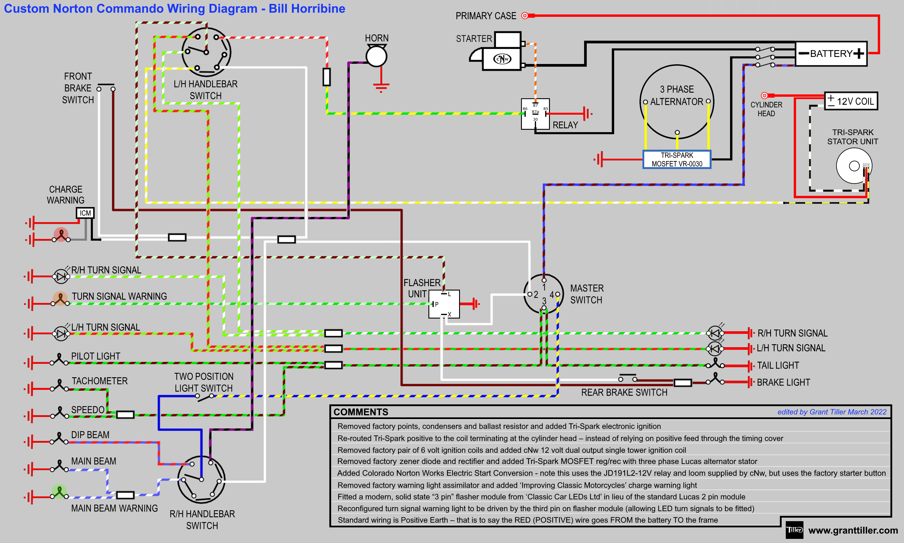
Wiring Diagram
Here is the Custom Wiring Diagram for Bill’s 1971 Norton Commando Long Range Fastback.
Custom Norton Commando Wiring Diagram – Bill Horribine PNG 3066×1841
This is available as a PDF too – it can be downloaded here.
Grant
I’m planning a new harness for a 1974 850 Mk2A Interstate. The component list is almost identical to Bill’s bike (CNW starter, three-phase generator, Trispark ignition and MOSFET reg/rec, charge warning light) although it will have two 6v coils and a standard two pin flasher unit. I’ll be using a positive ‘bus’ running the length of the bike, spliced into as required and with grounds at the rear light module, head steady and headlamp bowl. I have noted your comment that the only positive battery connection should be from the primary case. I’m trying to draw the harness showing the ‘bus’ and am having problems. Can you offer any advice how it should be done?
With thanks in advance.
Hi Trevor,
I have just finished building out a custom wiring diagram and positive earth ‘bus’ map with the alterations and upgrades you have for your bike.
It can be found here:
https://granttiller.com/custom-norton-commando-wiring-diagram-trevor-wray
Hope this helps!
Grant
Grant – many, many thanks! This is brilliant, and will be an enormous help. Thanks too for your advice on wiring technique, which I found really useful. The wealth of information and guidance that you offer to Commando owners is invaluable. Once again, many thanks! Trevor
Happy to help Trevor!
…if you have any pics of your bike, send them over – I’d be pleased to add them to the page!
Will do! Thanks again.