


Matt Rambow and his team at Colorado Norton Works make some beautiful stuff, and their latest creation – an Electric Start Conversion for the pre-MK3 Norton Commando is no exception.
The cNw kit, found here is actually very reasonably priced at $2,495 if you consider that it includes a belt drive primary.

As always with Colorado Norton Works, the quality of the fit and finish is second to none.
If you don’t want a highly polished finish, there are option for satin and matt black too.

Matt supplies a starter button with his kit, as the quality of the original switches were dubious when they were new. That makes it difficult for Matt to support, and guarantee the reliability, hence shipping his own.
However, of the people I have spoken to, most want to use the original handlebar switch gear, and make use of the ‘spare’ button that Norton themselves never got round to using (the MK3 used different handlebar switches)
Here follows the Norton Commando pre-MK3 wiring diagram with the addition of the Colorado Norton Works Electric Start Conversion
The 1971 and 1972 onwards diagrams use the original Lucas switch gear.
The 20M3 bike is not a good candidate for an electric start conversion, as the points location does not give ample clearance for the starter motor assembly to be mounted.
If you want to fit electric start to an older bike, either fit a later camshaft and timing cover so that you can move your ignition to the front of the bike, look into a crankshaft mounted ignition trigger, or fit a later engine.
Anything is possible of course, but i would suggest that the engineering work/re-work involved would make it non-viable for most, and probably not financially sensible either.
This pages includes some of the choice aftermarket parts that Matt recommends to his customers:
- Tri-Spark electronic ignition
- Dual output single coil
- Tri-Spark MOSFET regulator rectifier
- 3 phase Alternator Stator
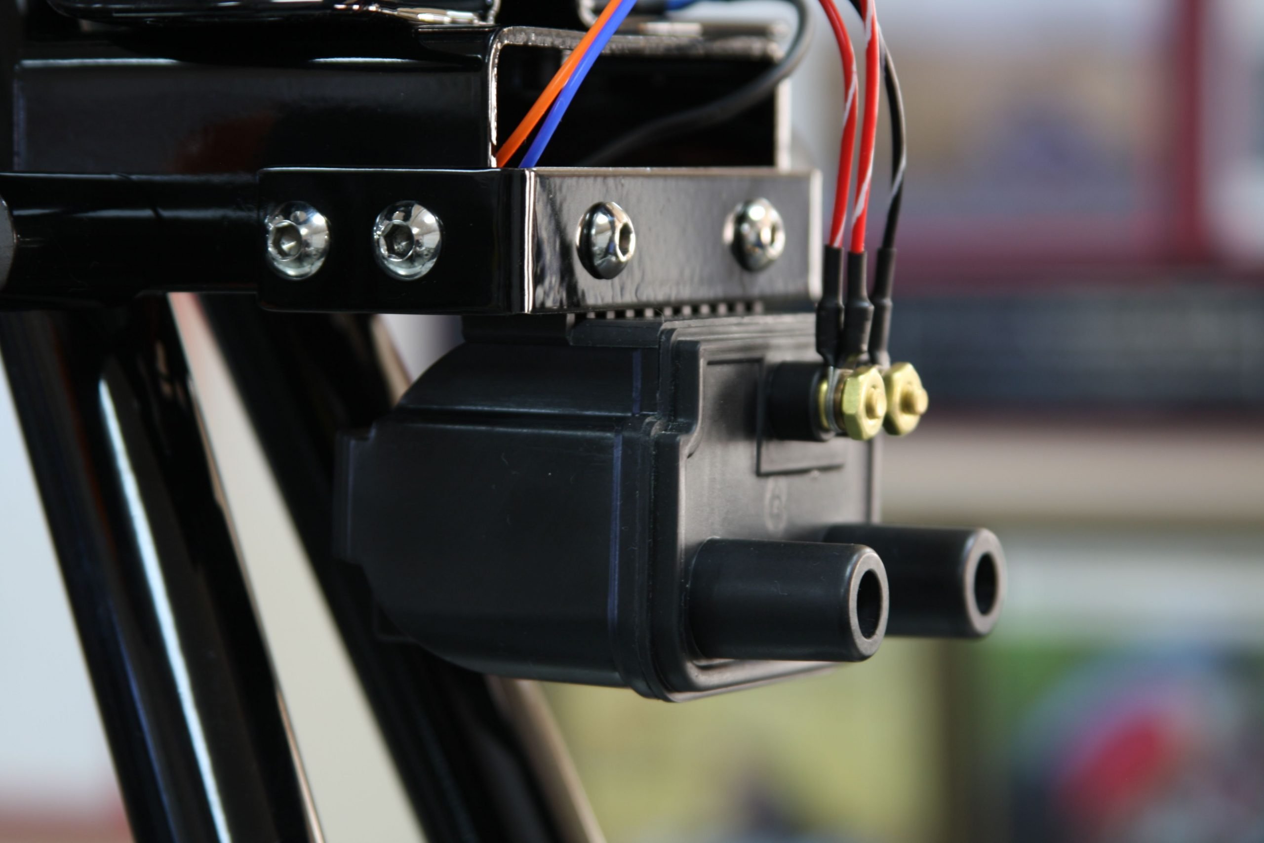
Electronic Ignition

The new kid on the block for Electronic Ignitions is Tri-Spark.
Well, I say new kid – they have been around since about 2009.
You can find the Tri-Spark website here.

The Tri-Spark unit is a one box solution – all the gubbins are mounted inside the points cover – no additional black box to try and hide under the tank, and very very simple to connect up.
The wiring is as follows:
| Wire Colour | Description |
|---|---|
| Red | This is the positive feed to the Tri-Spark unit. Most people attach this wire to one of the two fixing posts inside the points cover. I would personally recommend running an additional wire up to the coils and have drawn the wiring diagrams accordingly. |
| Black/Yellow | This is the negative feed to the Tri-Spark unit. This joins in to the White/Blue wire that used to feed the Ballast Resistor that you are removing. As standard, this goes up to the big connector block under the tank, where it’s joined to the White/Yellow that is the kill switch on your left side handlebar switch cluster. |
| Black/White | This is the negative supply FROM the Tri-Spark TO the coils. |
As with the Boyer, from a wiring perspective, the most important thing to note is that you will be moving from a pair of coils that are wired in parallel to series.
Originally, the points make and break the positive (earth) side of each coil in turn.
The Tri-Spark electronic ignition system uses a concept called “wasted spark” – with the two coils wired in series, they are energized together on every rotation of the camshaft.
You’ll note in the wiring diagrams below that the Ballast Resistor and Condensers have been removed as part of the conversion to Electronic Ignition.
Two major benefits of the Tri-Spark:
- a very low operating voltage – as low as 8 volts means your bike will still run with a less than optimal battery and charging system
- circuitry performs the electronic equivalent of advance and retard to make the bike easier to start and stop the possibility of kick-back. This makes it gentler on your knees, and kinder to electric start systems (aka the delicate Commando sprag clutch)
Single Coil
In lieu of the twin 6 volt coils, Matt recommends a dual output single tower coil (see on his Colorado Norton Works store)
It’s the brilliant Crane Cams unit and looks much neater.
Regulator/Rectifier
Matt used to recommend PODtronics, but switched to the Tri-Spark MOSFET reg/rec.
It is relatively new to market and more details can be found here Tri-Spark MOSFET
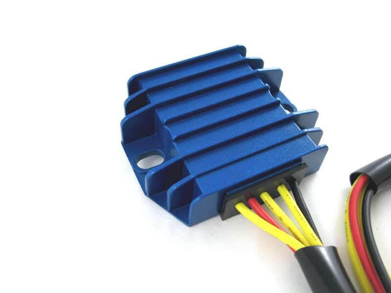
It is certainly easy to spot in it’s blue anodised heatsink!
There are five wires to connect:
| Wire Colour | Description |
|---|---|
| Yellow (x 3) | these are the AC input and pick up on the three wires coming out of the three phase alternator stator (connection can be any way round, as this is the AC side of the circuit) |
| Red | this is the Positive output and will join to one of the red wires in the harness |
| Black | this is the Negative output (known as the hot wire) – it will be wired to the NU (brown/blue) that goes back to the battery negative terminal via a fuse |
The spec on paper is very good, being able to handle up to 20 amps.
And the benefit of MOSFET is much more precise control of the charge voltage. I have done a deep dive into reg/rec types and behaviour which you can find here
Here are the wiring instructions for the Tri-Spark VR-0030 MOSFET regulator/rectifier.

Alternator

With electric start, Matt recommends a three phase alternator stator.
It’s a great option to go for and is far superior to the factory original single phase unit.
The spec is as follows:
- Lucas RM24
- 3 Phase
- 14.5 amp
- Part Number LU47244
- Also found under Part Number WW10192L
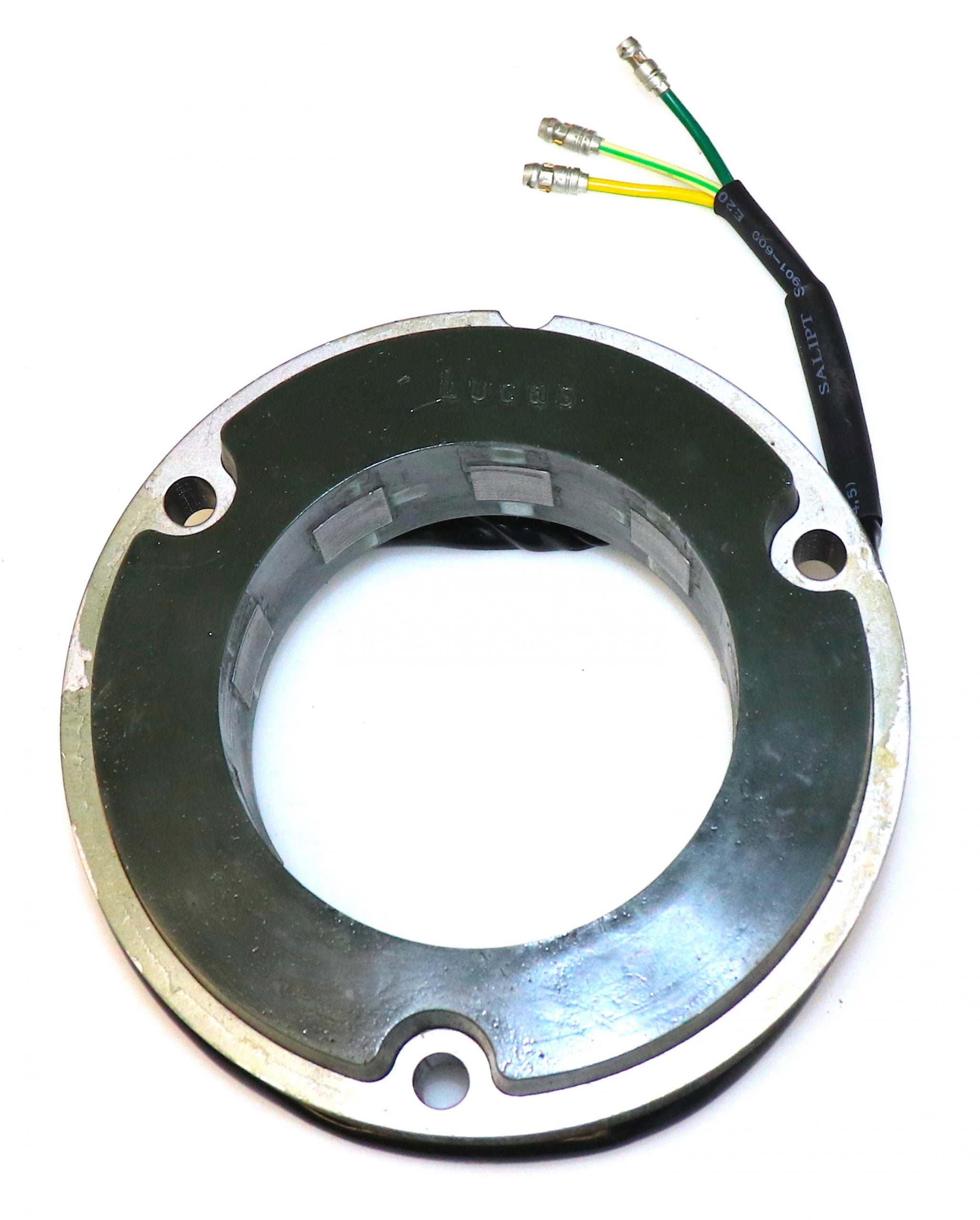
This stator is the high output version, putting out around 14.5 amps – this is a sound choice on an electric start bike or when you plan on fitting compnet that draw high, constant current, as the duration of most rides will be spent recharging a depleted battery.
In addition, because it is a three-phase unit, output is produced at a much lower RPM making this an ideal solution for around town and in stop start traffic conditions.
As always, we recommend that you ride with your headlight on, as this will always help with the longevity of the components that make up your charging system.
Warning Light Assimilator
The factory warning light assimilator is not compatible with most modern regulator/rectifiers and the PODtronics is no exception so it has been removed from the schematics.
Plus, there is the matter of what the WLA is actually doing, and how much use that is.
The WLA is looking purely for some AC output from the alternator stator (about 6 ½ volts AC) it is not designed for a three phase stator either.
It gives you no information about the charging (i.e., the regulator (zeners) and rectifier)
It gives you no information about the state of the battery.
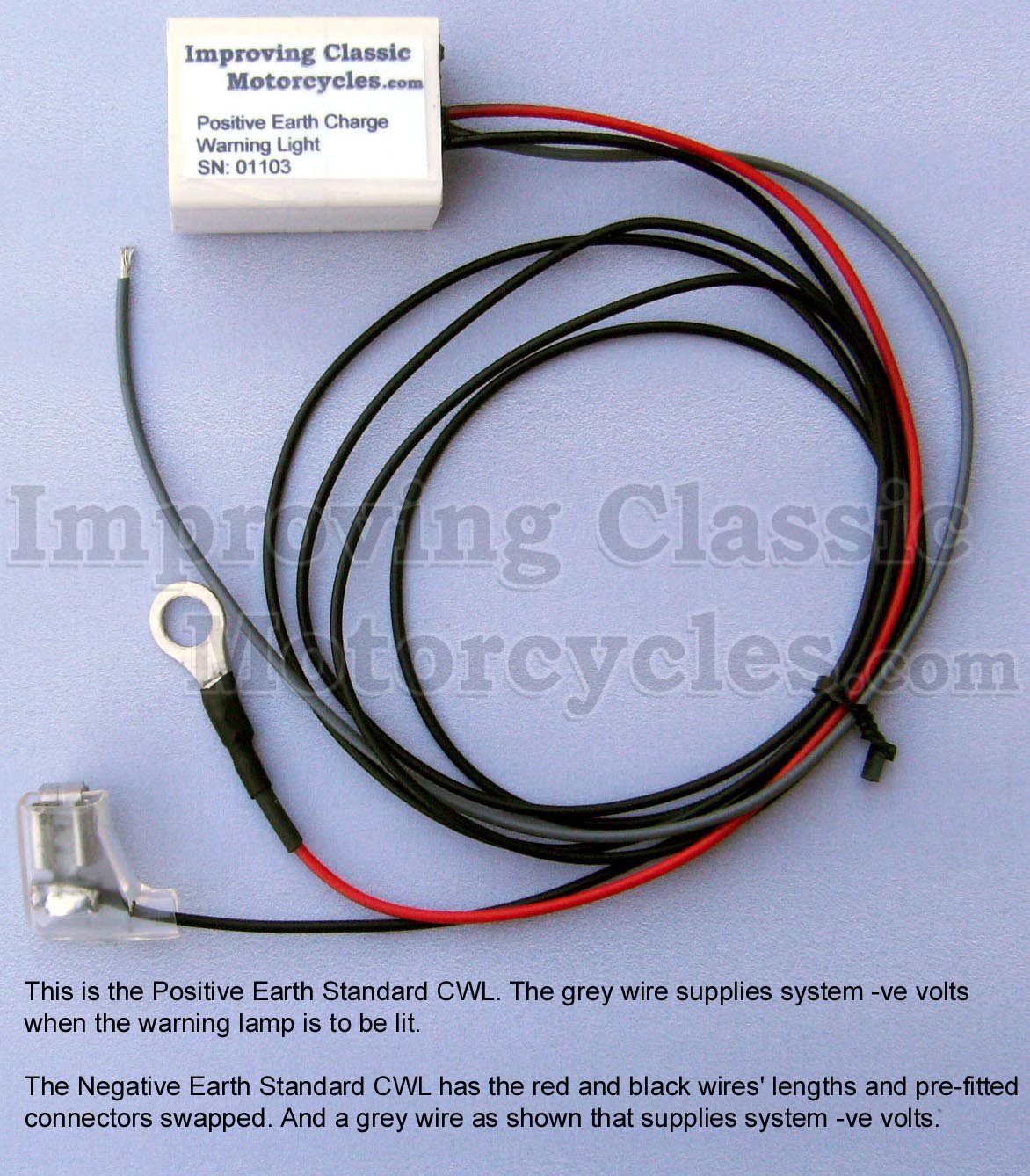
Charge Warning Light

I have taken the liberty of adding an ICM Charge Warning Light to the schematics – I can certainly recommend the Improving Classic Motorcycles charge warning light as a brilliant alternative.
I use them myself, and have had a good experience with them.
The nice thing about the Improving Classic Motorcycles unit is that you can retain the original warning light – so it looks totally factory (this for me is an important factor with the MK3 with it’s quirky little instrument panel).
It gives you a lot more useful information about the state of the battery and charging system compared to the standard assimilator unit, which looks for AC output from the alternator stator only.
1968 Norton Commando Wiring Schematic + cNw electric starter AND Tri-Spark ignition AND Tri-Spark reg/rec
These are the pre-1971 bikes and have the ammeter in the headlight shell, as well as the Wipac Triconsul type handlebar switch.
The wiring is very simple, and more like the Atlas than what came to be familiar with the Commando.
Note that I have included the Front Brake Switch as standard – this was a US requirement, that didn’t appear on the earliest UK bikes.
1968 Norton Commando Wiring Schematic + cNw electric starter AND Tri-Spark ignition AND Tri-Spark reg/rec PNG 5600×3960

This diagram is also downloadable as a PDF from HERE

1971 Norton Commando Wiring Schematic + cNw electric starter AND Tri-Spark ignition AND Tri-Spark reg/rec
This is often referred to as the “Interim” model.
It is distinguishable by the three pin master switch (ignition key switch) which was Lucas part number LU39565.
These were made ONLY for the Norton Commando, and are no available as an aftermarket replacement.
If you are not comfortable rebuilding the switch, most people choose to go for the LU30552, which IS readily available.
You can find an article on ignition switches here, that may be of interest.
1971 Norton Commando Wiring Schematic + cNw electric starter AND Tri-Spark ignition AND Tri-Spark reg/rec PNG 5600×3960

This diagram is also downloadable as a PDF from HERE
1972 onwards Norton Commando Wiring Schematic + cNw electric starter AND Tri-Spark ignition AND Tri-Spark reg/rec
The 1972 onwards schematic covers 750 and 850 bikes and has the much more familiar four pin master switch (ignition key switch)
1972 onwards Norton Commando Wiring Schematic + cNw electric starter AND Tri-Spark ignition AND Tri-Spark reg/rec PNG 5600×3960

This diagram is also downloadable as a PDF from HERE
NOTE:
A couple of points about the way these diagrams have been drawn:
- The diagrams on my site are schematics – the components are not drawn in the physical location on the bike. Instead they are drawn in locations that make the diagram the easiest and most logical to follow.
- Where the same colour wire goes in to and out of a single connector, that connector has usually been omitted from the drawing.
It’s obvious on the bike, is easy to spot and easy to troubleshoot.
Leaving them off the diagrams makes them a LOT easier to read, and considerably less cluttered. - Wherever the earth or ground side of a component goes back to the battery, the drawing shows a red earth symbol:

In reality, this could be connected either to a red wire in the bike’s wiring harness (loom) OR it could be attached to the frame or engine of the bike.
I have shown the red earth symbol each time in order to massively simplify the diagram, and make it a lot easier to understand for everyone.
I have also coloured them red as a gentle reminder that these bikes are wired positive earth!
Grant, what program are you using to do these? I’m specifically interested in the ability to get the two colors on the wires. Thanks, David
Hi Grant,
Further to my recent last email – apologies. I found the wiring diagrams after I sent the email!
Just a quick question.
Do I need to fit a ‘noise filter (?)’ to the system to prevent misfiring problems with the Trispark system or just use a different rec/reg to the Podtronics.
regards
David
Hi Dave – great to see you have found the cNw wiring diagrams.
If you have anything different to what I have listed here, don’t hesitate to reach out.
If your Podtronics and Tri-Spark combo are fitted and are not showing any issues, then you are good to leave everything exactly as it is.
The issue does not seem to manifest on all Podtronics units, just a few of them.
Thanks Grant, your reply is appreciated.
I haven’t purchased any components yet and might just get the new stator and MOSFET kit from TriSpark when I get the new ignition system. I imagine I would then just substitute out the Podtronics reg/rec in the diagram.
Regards
David
David,
I really like the Shindengen open-type reg/rec.
I use them myself, recommend them to others, and have never seen one go bad.
There are a lot of counterfeit units on the market, so be careful.
Maybe order one from Jack at Roadster Cycle (https://www.roadstercycle.com), and get him to ship it to Matt Rambow at Colorado Norton Works, to include in the box to you in Australia.