

A nice upgrade for a bike that maybe getting harder to start as you get older is electronic ignition.
This article covers that upgrade, together with a few other choice modifications that will make your bike easier to live with.
Whilst the article was written with the Norton Dominator in mind, everything covered is true for most brit bikes of the time, so this might be a useful page for non-Norton people too.
Electronic Ignition

The new kid on the block for Electronic Ignitions is Tri-Spark.
Well, I say new kid – they have been around since about 2009.
You can find the Tri-Spark website here.

The Tri-Spark unit is a one box solution – all the gubbins are mounted inside the points cover – no additional black box to try and hide under the tank, and very very simple to connect up.
The wiring is as follows:
| Wire Colour | Description |
|---|---|
| Red | This is the positive feed to the Tri-Spark unit. Most people attach this wire to one of the two fixing posts inside the points cover. I would personally recommend running an additional wire up to the coils. |
| Black/Yellow | This is the negative feed to the Tri-Spark unit. This joins in to the ignition key switch. |
| Black/White | This is the negative supply FROM the Tri-Spark TO the coils. |
The Tri-Spark electronic ignition system uses a concept called “wasted spark” – with the two coils wired in series, they are energized together on every rotation of the camshaft.
Alternatively you can go for a dual output single coil, and simplify things even further!

Two major benefits of the Tri-Spark:
- a very low operating voltage – as low as 8 volts means your bike will still run with a less than optimal battery and charging system
- circuitry performs the electronic equivalent of advance and retard to make the bike easier to start and stop the possibility of kick-back. This also makes it gentler on your knees!
Magneto Replacement
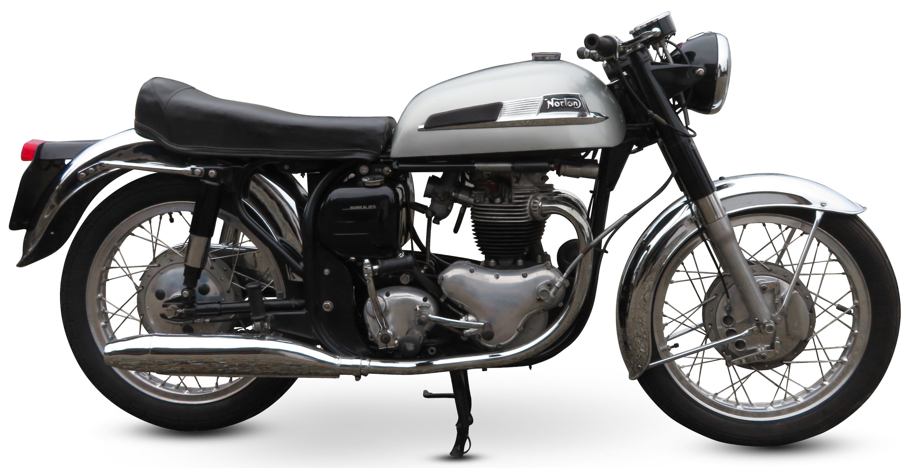
When you are replacing a magneto or distributor in favour of electronic ignition, you will usually need to strip out any advance/retard, and use a replacement housing.
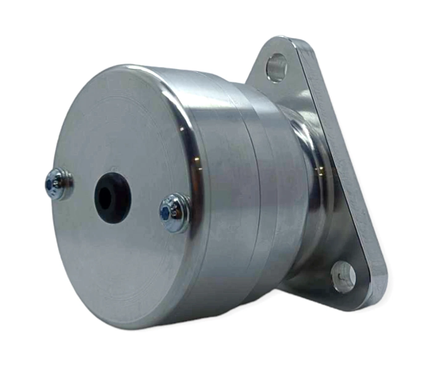
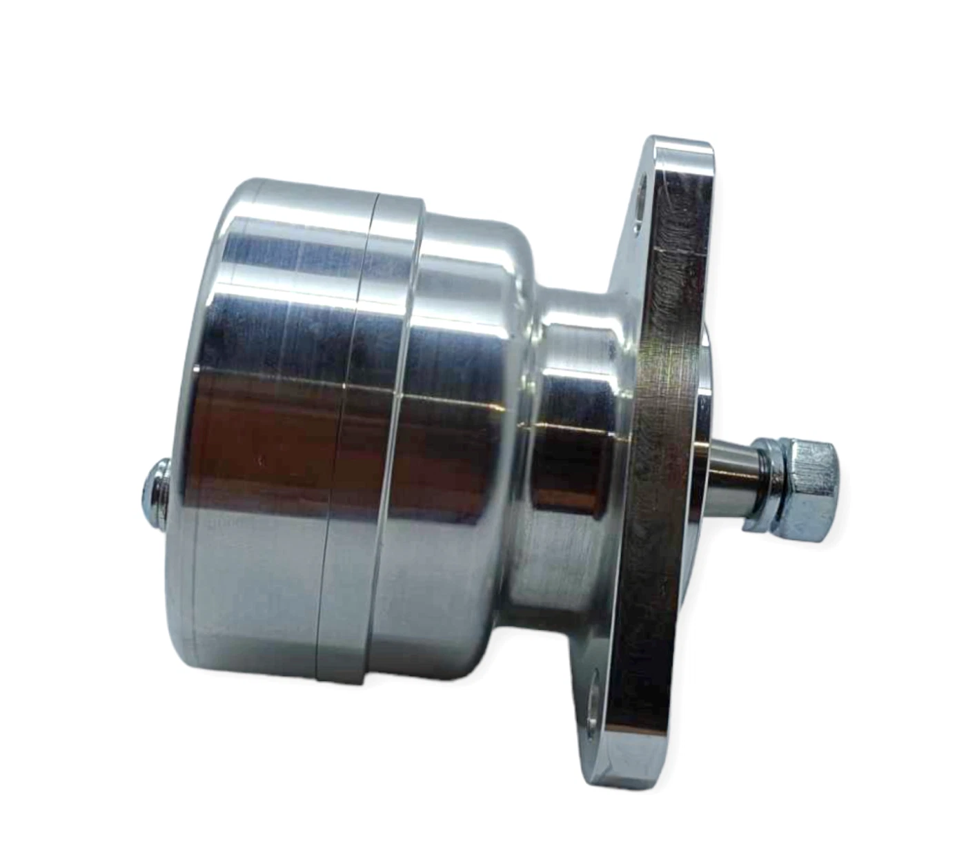
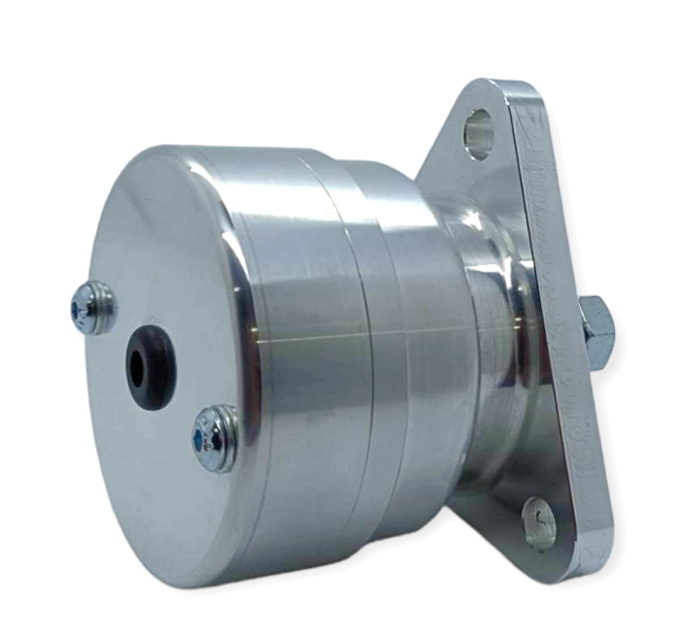
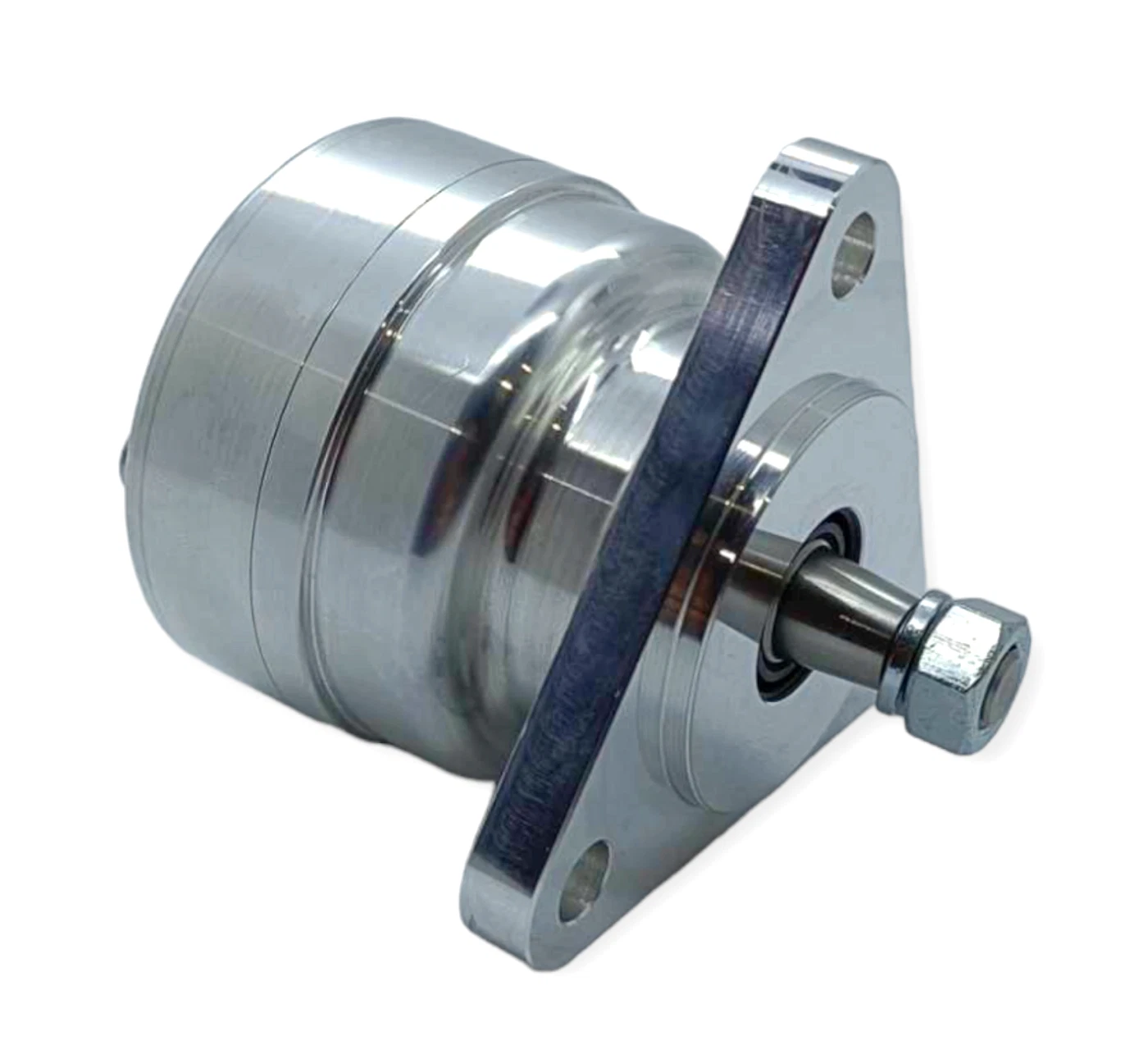
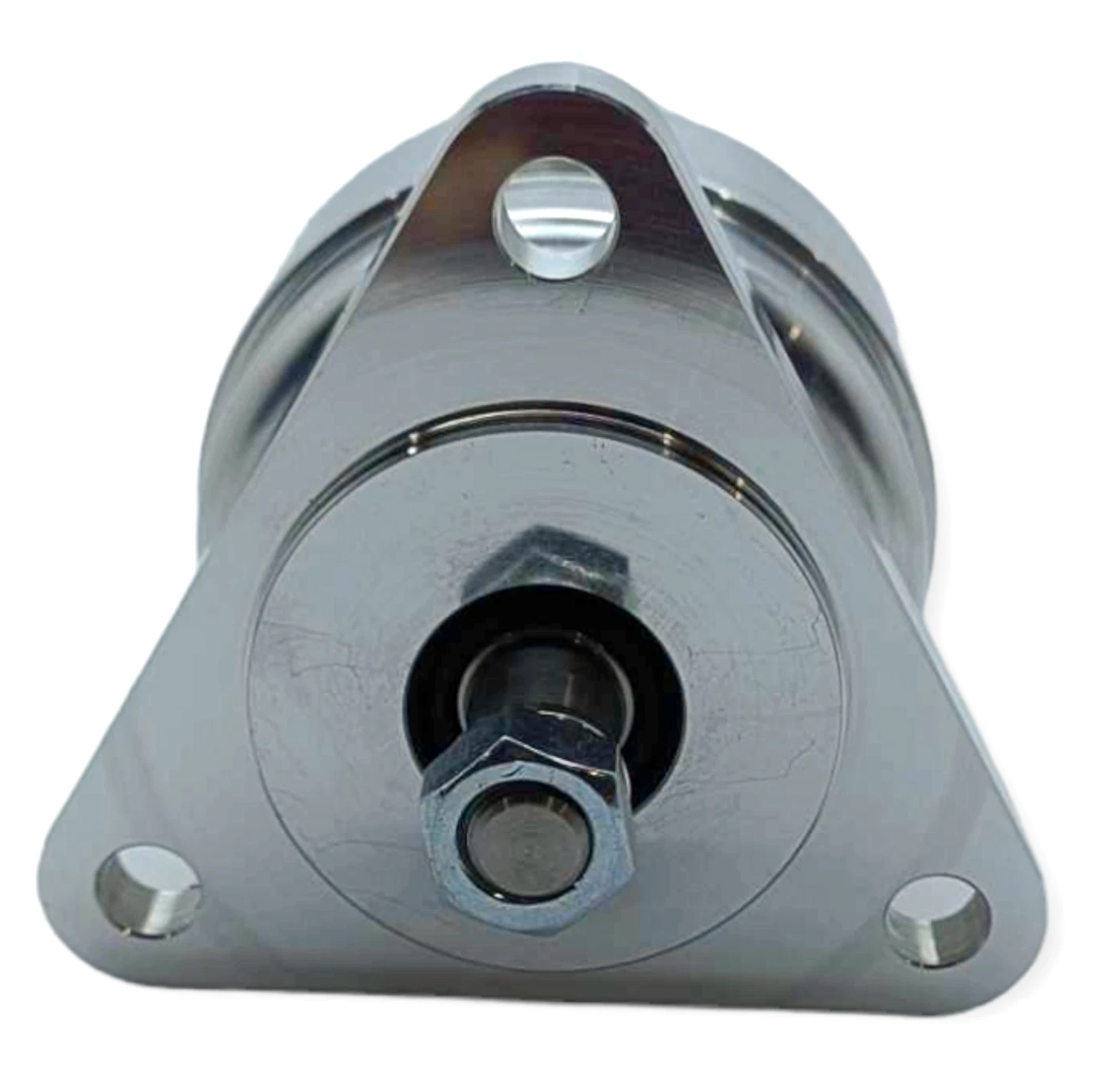
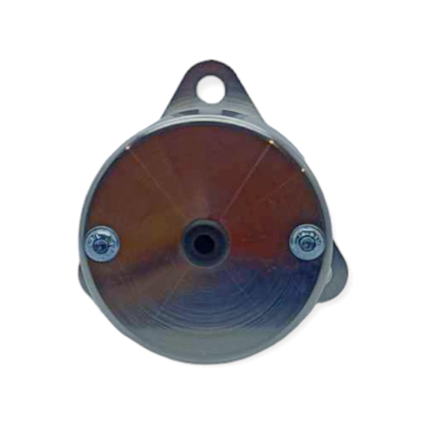
I have used the Wassell K1F/K2F magneto body replacement in this case, which is a decent and reasonably priced piece of kit.
It’s made from billet aluminium, and has a silky smooth sealed bearing.

There are plenty of options other here – Wassel under the Lucas brand have started selling a dummy magneto body that will house an electronic ignition. It is spendy, but a super thing.
Tri-Spark (the manufacturer of my choice in ignitions) have also started selling a “Magneto Replacement Kit” which includes ignition, coils and the magneto body, all in one box. It looks superb.
Alternator
It’s a personal choice, but I really like to specify a three phase alternator if I am rebuilding a bike.
The chances are that your single phase one, or your 6 volt one has seen better days by this point, so treat yourself to a new stator and rotor.
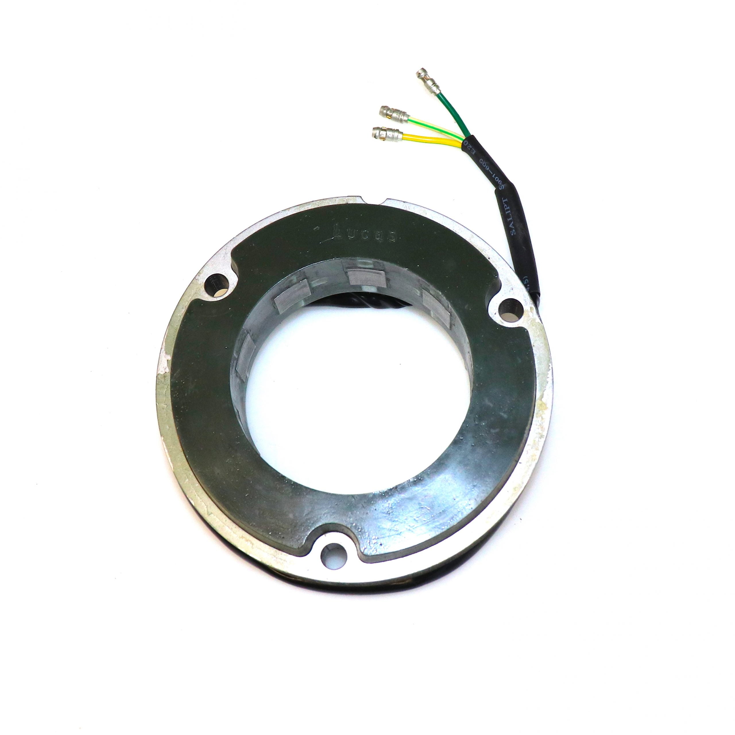
Three phase is a great idea for modern stop start traffic and lower speed around town and city riding, because you are charging at a lower RPM than the equivalent single phase unit.
Be careful that you don’t over spec the charging circuit though – bigger is not better in this case, and it is important that you are putting back in roughly the same as you are taking out!!!
The Lucas LU47252 (Wassell number WW10193L) is a 10.5 amp stator, so roughly the same spec of the original RM21 10 amp single phase stator that most of these bikes of the era would have had.
There is absolutely no need to go up to the 14.5 amp high power version unless you have a bike with electric start.
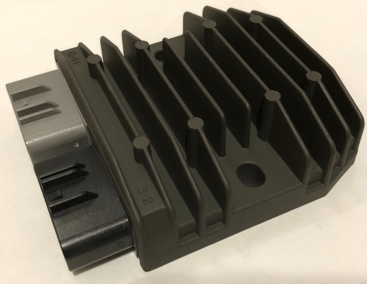
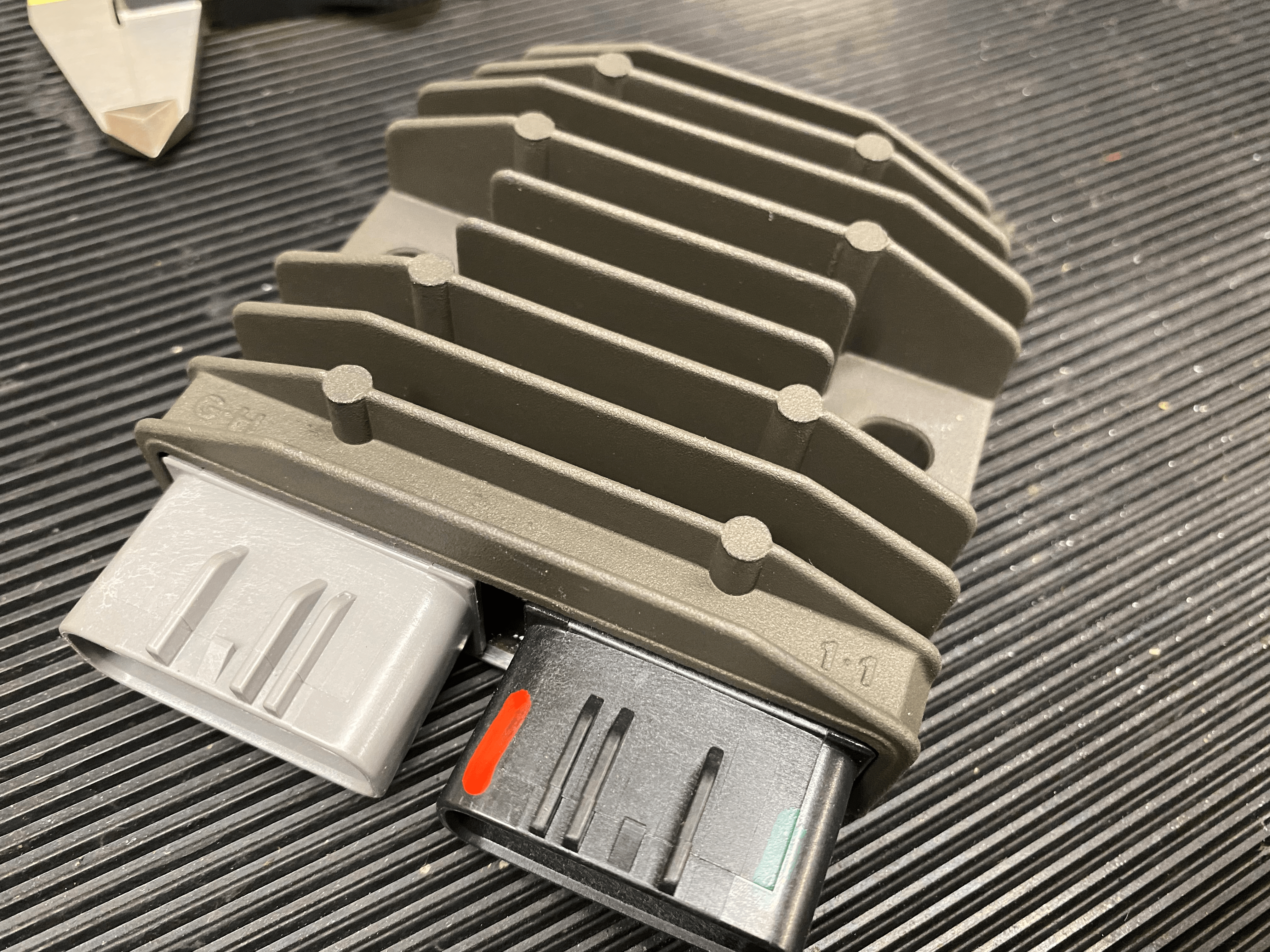
Regulator/Rectifier
There are a lot of reg/rec units on the market, but for me by far my favourite weapon of choice currently is the superb Shindengen SH775 regulator/rectifier.
I have written about open-type (also referred to by some as series-type) reg/recs extensively on this site ‘vs’ the much more common short-type alternative, so I don’t need to spend time covering the benefits here.
But for me, it is the best possible choice in terms of longevity, robustness and low maintenance.
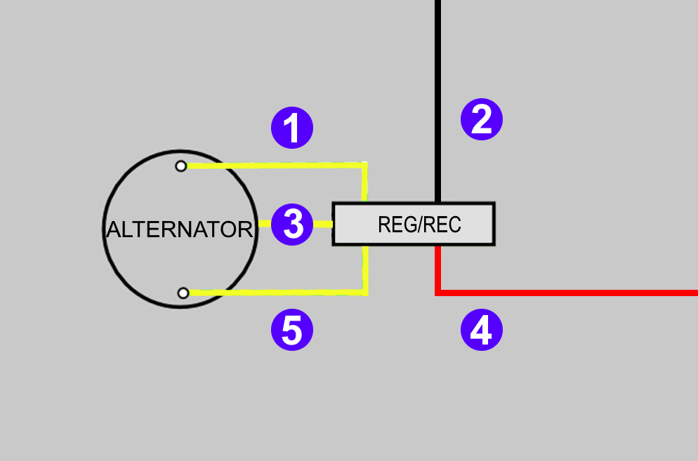
Wiring these up is simple:
- 5, 3 and 1
For connection to a three phase stator, the wiring order of the AC inputs don’t matter.
If you use this with a single phase stator, connect the two wires to any three of these terminals. - The black and red definitely do matter though!
- 4
The red (positive/earth) pin is toward the centre of the unit. - 2
The black (negative) pin is on the outside of the unit.
- 4
The Shindengen is wired in the same way as most aftermarket reg/rec units:
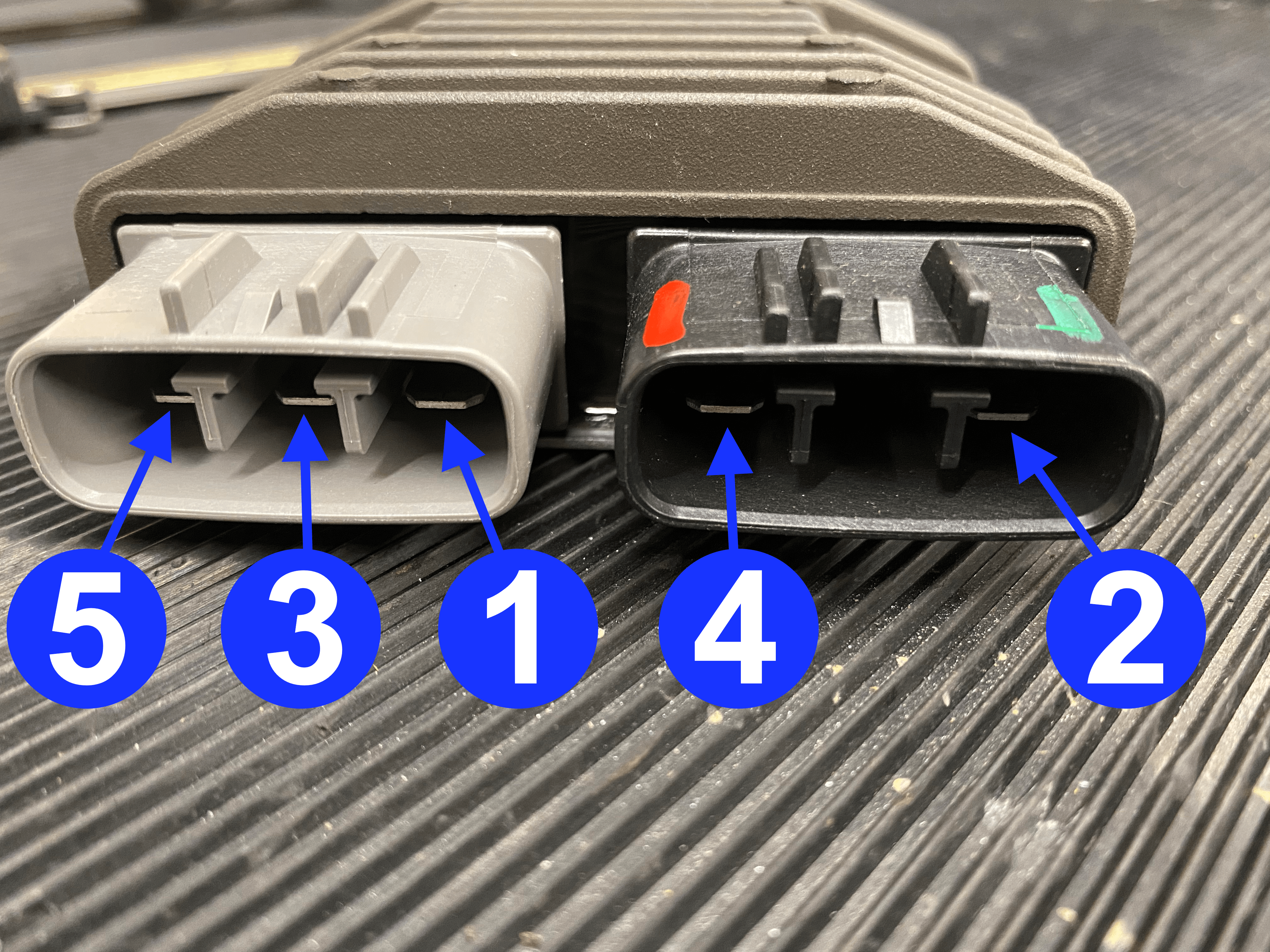
As there is no electrical connectivity to the heat-sinking metal enclosure, this unit is suitable for use on positive earth or negative earth bikes.
Battery
I am a huge fan of the Motobatt AGM battery.
The Absorbed Glass Matt battery is sealed, so no worry about topping it up, venting it, or spilling battery acid on the paint.
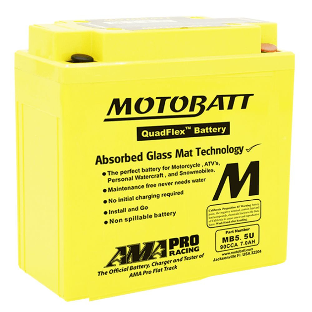
These AGM batteries are superb over the winter months – no need to keep them on a trickle charger or anything like that.
Just give it a full charge using a decent quality charger (I like CTEK who can be found here) the night before your first ride of the new season, and you’re good to go for the year!
As an example, for the Dommie 650ss, we chose the MotoBatt MB5.5U AGM
This particular battery is pretty small in size (13 ½ x 6 x 13 centimetres) which meant that by playing with the oil tank and battery box mountings, we could slide the battery down between the two quite easily.
The battery box was now totally empty, and could be filled with a decent sized tool roll!
Key Switch
It is very difficult to secure a classic bike, but a key switch is a visual deterrent if nothing else.
In all honesty, these bikes don’t get left in public where a chancer would steal it anyway.
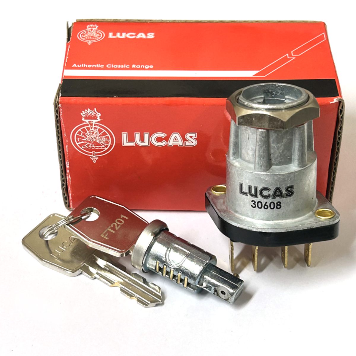
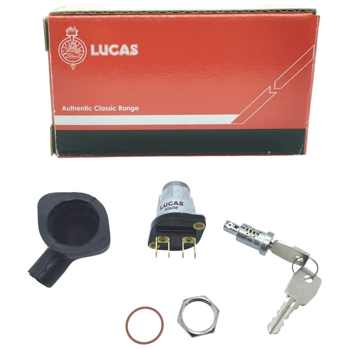
In the setup I have here, I have used the Lucas 30608A key switch. It’s a simple on/off switch, is robust, can take a decent amount of current and is common used on 60s bikes.
Of course, if security isn’t your thing, and you don’t want to worry about losing a key, you could very easily swap this out for something like the Lucas LU31780 switch which will match the style of the headlight switch.
Charge Warning Light
Instead of an Ammeter, I have used a Charge Warning Light.

My preference here are the brilliant little units from www.improvingclassicmotorcycles.com – this particular one is the Tri-Color LED which shows:
- less than 11.1V = slow red flash
- 11.1V – 12.6V = steady red
- 12.6V – 15.4V = steady green
- 15.4V – 16.1V = steady yellow
- above 16.1V = eye catching yellow flash sequence
Here is a link to a video on the ‘Improving Classic Motorcycles’ website.
To be honest, with a decent alternator, a good battery and the engine running totally independently off the Magneto, this charging system is totally over engineered.
My goal here though is literally fit and forget!
Headlight Switch
I went for the standard Lucas toggle switch here – familiar on most bikes of the time, and a very robust and long lasting item.
The LU31788 I use here is a three position Off-On-On switch
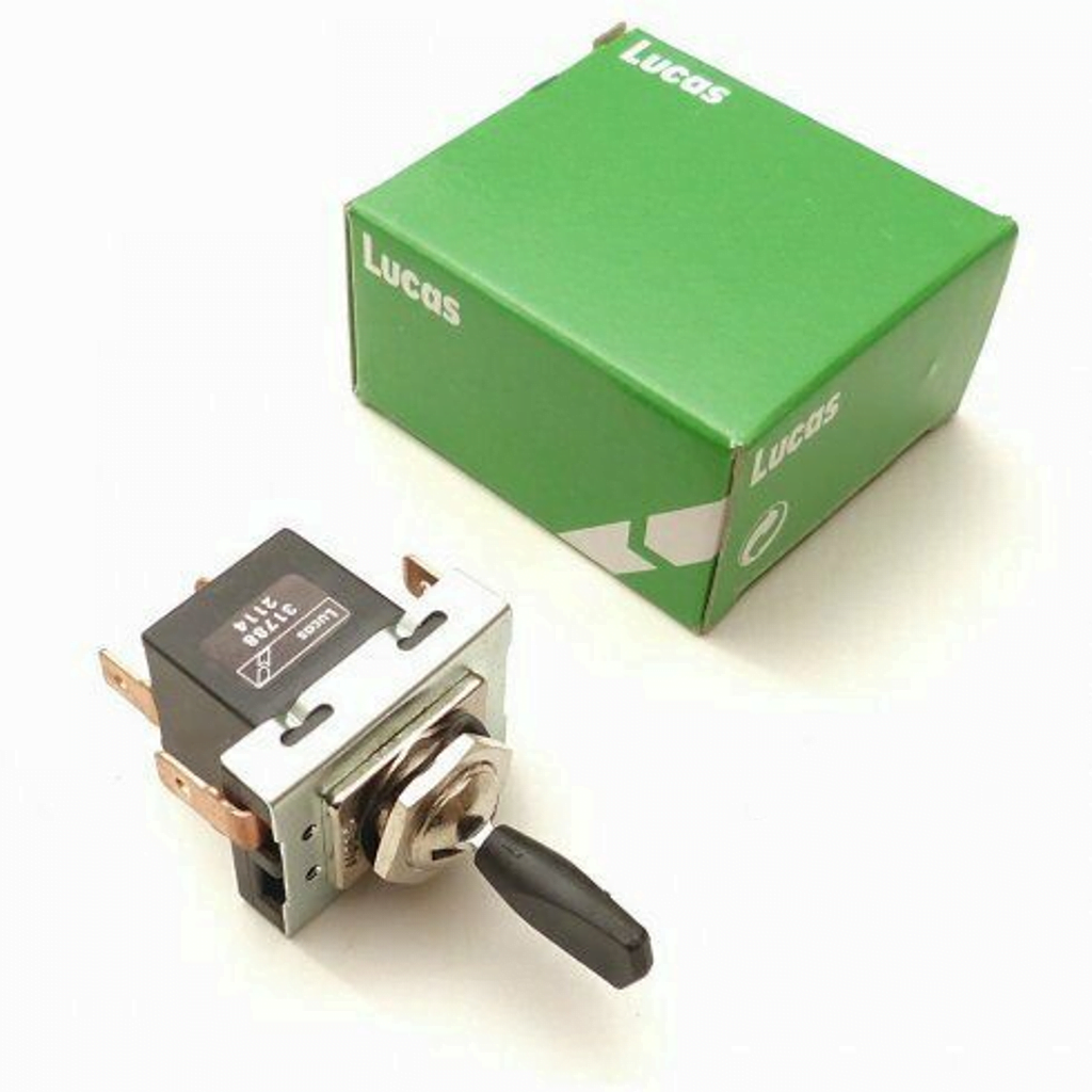
The lights turn on and off via a traditional Lucas 57SA toggle switch mounted on the headlight:
- (1) Off
- (2) Pilot Light
- (3) Dipped Beam
Be careful with part numbers if you are buying new – 57SA is the type (i.e., what it looks like, length of the switch toggle blade, size of mounting hole etc)
Here are the pinouts for the switch in the different positions:
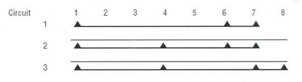
There are several part numbers available under this type, some are two way (off-on) others have a different numbewr of connection terminals on.
The LU31788 is the part number you need!
Handlebar Switch
I have gone for the Wipac Ducon switch on the left handlebar to toggle between dipped beam and main beam.
It’s also the home of the Horn button.
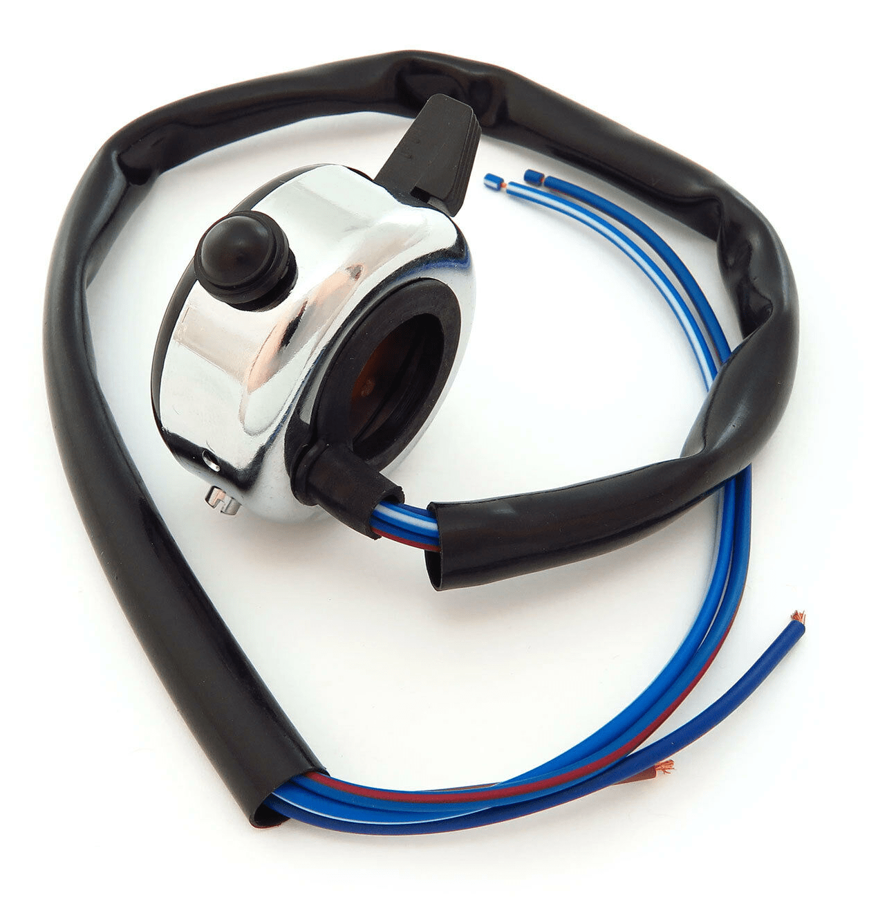 | 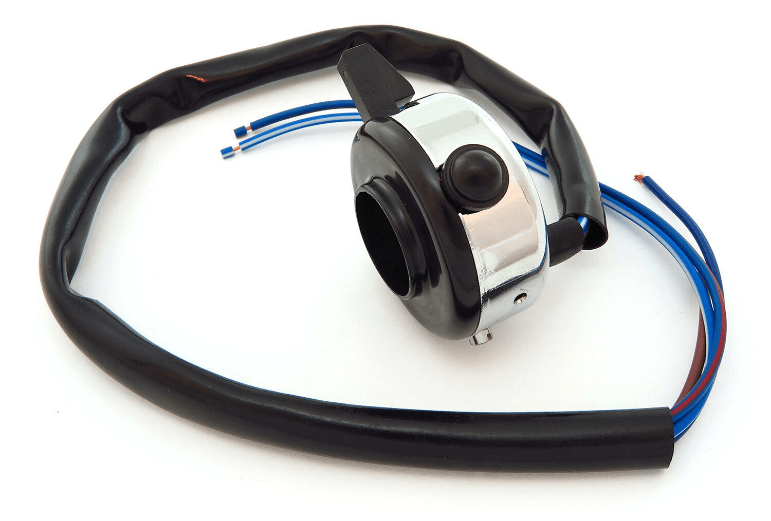 |
In my opinion, these are the best of a bad bunch – all of the aftermarket ‘retro’ handlebar switches are really awful quality – especially the Lucas (Wassell) ones which is why I have gone up the Wipac route here.
Earth
Anyone that follows my blog will know that I am always rabbiting on about earthing.
On the Norton Commando (the topic of most of my posts) we are blessed with a bit of forward thinking.
Engineers at Lucas and Norton were worried about the Isolastic drivetrain mounting causing earthing problems, so in the main part ran earth wires (which should really be referred to as positive feed wires) between electrical components on the bike, rather that earthing out through the frame.
With one or two minor exceptions, this resulted in a reliable and robust electrical system.
I really like the concept of not relying on the frame for the ‘earth’ so whenever I can, I will always recommend running separate wires instead of earthing out to the frame.
It gives you a much more reliable electrical system!
Fuses
The reg/rec is on it’s own dedicated fuse which is wired directly to the battery.
The beauty of doing this is that if, for whatever reason there is an issue with the charging system, you can pull the fuse and still use the lights to get you safely home on battery power alone (the recommended battery above will give you a couple of hours).
Also, if there is a failure of the reg/rec, there is no risk of overcharging and boiling the battery dry – it’s a smart move.
I have found issues with the glass-style fuseholders in the past – the springs become weak over time, and eventually the circuit becomes intermittent.
As the fuse disconnects and reconnects to the contacts, a small amount of arcing occurs – over time a layer of ‘soot’ will build up over the contact patch, which in itself acts as an electrical insulator.
This can impact all sorts of things, not least an undesirable lighting disco effect when you ride over bumps!
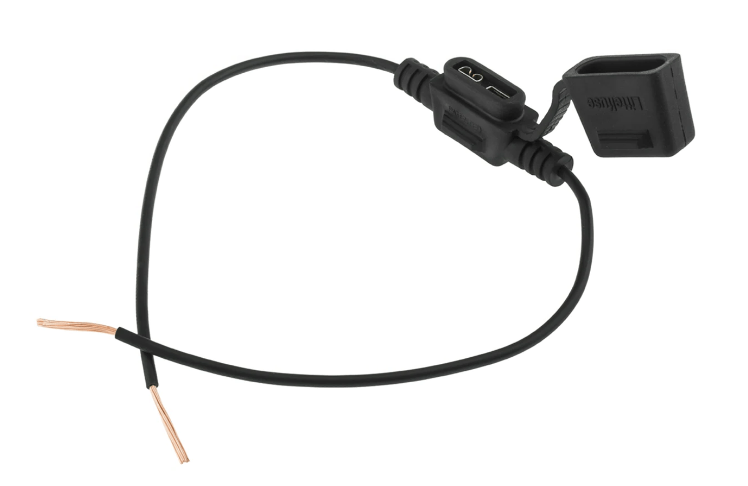
I would recommend using automotive blade type fuses all round instead of the original glass type used on these bikes.
These are great, as blade fuses are available in every garage and petrol station, and are very resilient to vibration.
A 15-amp fuse in each will be fine.
Wiring Diagram
I have drawn two flavours of diagram here – the standard and more familiar positive earth diagram.
But also, a negative earth version too – this is useful if you have other, more modern bikes in the workshop alongside your 60s brit bike and are worried about flipping between positive earth and negative earth bikes.
I have kept the wiring standard, using period correct colour codes wherever I can.
Basic Motorcycle Wiring Diagram (Electronic Ignition) POSITIVE EARTH – PNG 3066×1841
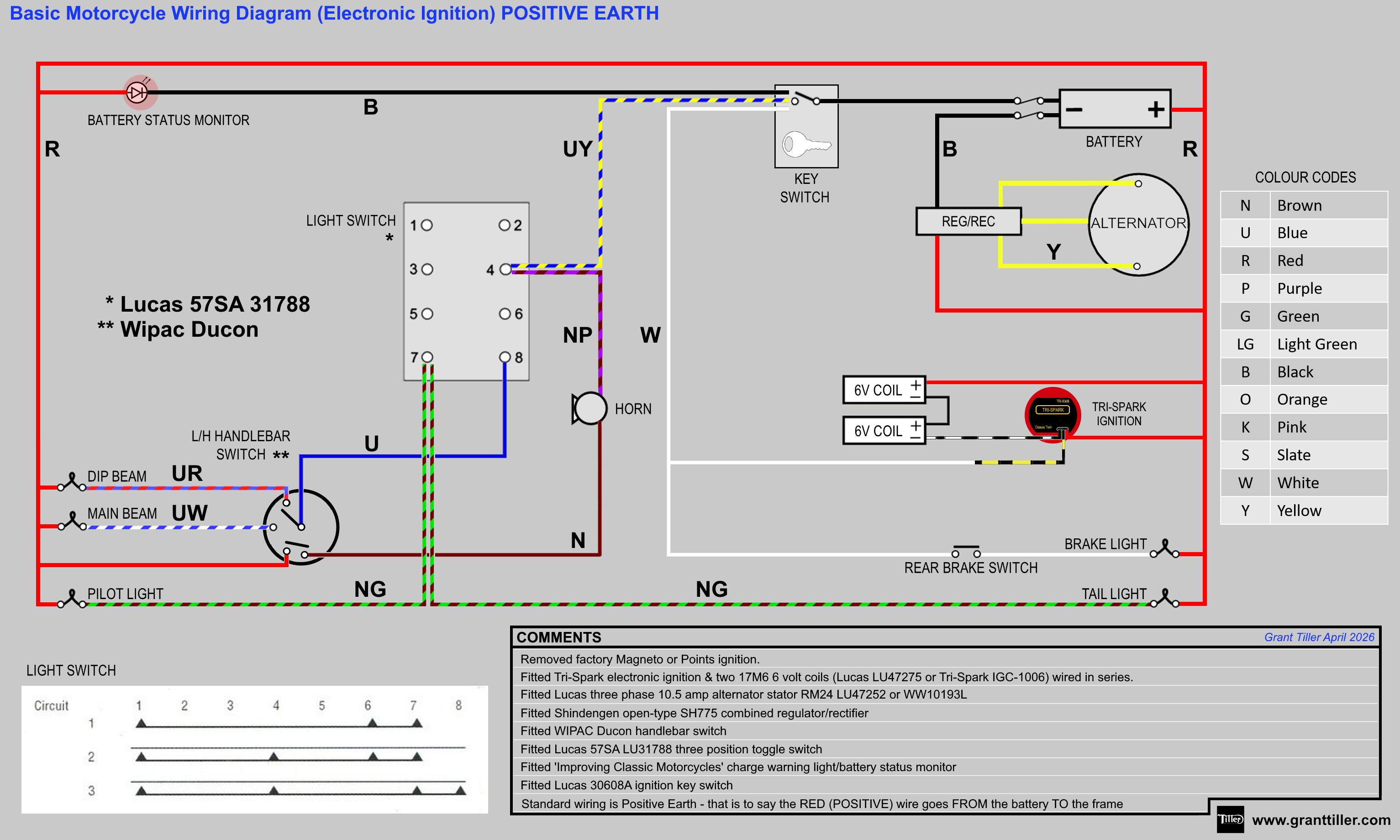
This is also available for download as a PDF
Basic Motorcycle Wiring Diagram (Electronic Ignition) NEGATIVE EARTH – PNG 3066×1841
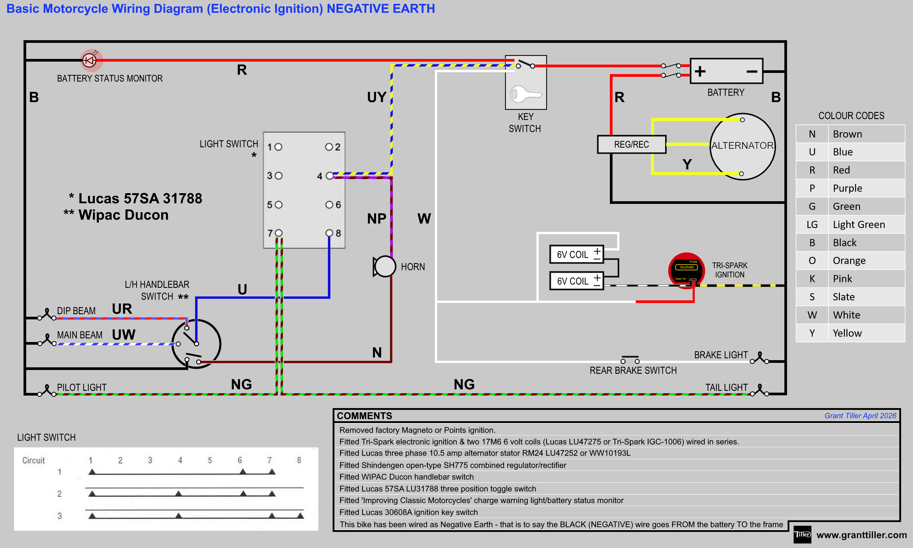
This is also available for download as a PDF
This article is from a series of three covering Simple/Basic britbike wiring diagrams:
- Simplified British Motorcycle Wiring Diagram
- Basic Cafe Racer Wiring Diagram
- Basic British Motorcycle Wiring Diagram with Electronic Ignition
As always don’t hesitate to reach out if you need any help or advice.
2 thoughts on “Basic British Motorcycle Wiring Diagram with Electronic Ignition”