
It is important to use the correct value fuses and cables when you are working on your bike.
If you are rewiring a bike from scratch, put some thought into how you are going to set about it.
The Lucas wiring on our bikes is fifty years old and still going strong – that’s testament to excellent quality and well thought through (usually!) design.

Fuses
I recommend using automotive blade type fuses – these are great, as blade fuses are available in every garage, and are very resilient to vibration.
You can use a 15 amp fuse for most Commandos, unless you’ve got something fancy like heated clothing, or a Lucas RITA electronic ignition (which can be quite power hungry)
Fuse values are important, and watch out with the old style fuses.
Our workshop manual specifies a 35-amp fuse:

This was written in the 70s for a 70s british bike
It did not take into consideration that a US fuse is rated in a different way!
The British standard was to show the blow value on the fuse, and in the manual – not it’s continuous rating.
The US standard (which was subsequently adopted internationally) is to show the continuous rating value on the fuse, and in the manual.
Some fuses, back in the day showed BOTH their continuous rating value AND their blow value, but this was certainly not always the case.
To this end, I see MANY bikes fitted with the wrong value fuse – a 35-amp continuous rated fuse will blow at 70 amps… a long time after every cable on the bike has melted.
Modern blade type fuses are labelled and referred to by their continuous rating. Everywhere. Worldwide.
So, you know where you are, and there are no nasty surprises.
Ring
In my article Bad Earth I talk about how Norton and Lucas dealt with the positive feed, and how they didn’t rely on the frame as the positive feed from the battery – this was good thinking, and innovative for the time, however I do feel that this idea can be tweaked a little.
In the standard wiring harness, you’ll see that quite often a component will have two red positive cables attached to it.
In simplified terms, it looks like this:
Think of the standard setup like your home electric ring main – the first cable feeds the component, then the second cable leaves it and goes on to feed the next one down the line. It is sometimes referred to as daisy-chaining.
There are a couple of issues with this methodology:
- If a cable is broken at any point, it can break the chain and interrupt the feed to the components further down the line.
- Breaking this connection is quite likely given the fact they are terminated with male bullet terminals, and are pushed into female bullet connectors – the multi-way versions of these can become very brittle and unreliable as the rubber housing perishes and breaks down.
- Having more than one connector at the component itself can put stress and strain on it – don’t forget, this is considered a harsh environment with high vibration, high temperature and sometimes grease and oil.
Bus
If I am making my own harness, or part of a harness, my preference is to make a BUS, and tap in to it where I need a positive feed.
Again, simplistically, it looks like this:

And for an electric start bike, it would look like this:
The advantage of a positive bus like this is that the branch connections (which I twist, solder and heatshrink as described below) are made along the cable that runs from front to back of the bike.
This is taped, like the rest of the harness, so the connections are hidden, strain relieved, and protected from moisture and dirt ingress.
Not having two connectors at each component takes a lot of bulkiness away from the component itself, making it look a lot neater and tidier.
And, if for whatever reason one of the cables that feed a component got broken, cut, or the connector failed, it would not impact the positive supply through the rest of the bike.
When you splice into the cable to feed the positive to an individual component, you can use a lighter gauge cable that is rated for the maximum current that particular part will draw.
For example, the turn signals can have an 18-gauge cable – 1mm² will handle 8.75 amps and be more than enough.
Those old 21-watt lamps used in the turn signals will draw no more than 3.5 amps.
Wiring Technique
When I am making up looms and harnesses from scratch, I like to minimize the number of connectors I use – ideally using them only at the point the cables plug in to the components themselves.
This feels contrary to what they did back in the 60s on bikes, where you seem to run into connectors for the sake of it – these are potential points for moisture ingress, terminal corrosion (the dreaded verdigris) and ultimately failure.
If I am splicing like in the case of the positive ‘BUS’ (covered above) that I like to run from front to back of a bike, I like to bare the cable using wire strippers where I want my splice to be, I then twist the junction wire around the bared section, solder it, and use an adhesive lined heatshrink sleeve over the top which will protect the joint from moisture ingress and provide decent strain relief.
I feel that mechanically twisting the cables as I do, and then strain relieving them so well means there is zero risk of a soldered joint becoming dry or failing – I have certainly never had a failure in many years.
While soldering cables on planes, cars and bikes is wrong (new vehicles use 100% crimping as their resistance to vibration is far superior) I am okay doing these joints within a harness – the bundle of cables, heatshrink sleeving, tape wrapping and minimal use of solder makes sure this is a good, strong, and reliable joint that will not fail.
It helps to do this in a clean workshop with new cable – again it makes sure you are building something that will last fifty years or more without any cause for concern.
Here are some pics of my splicing procedure:


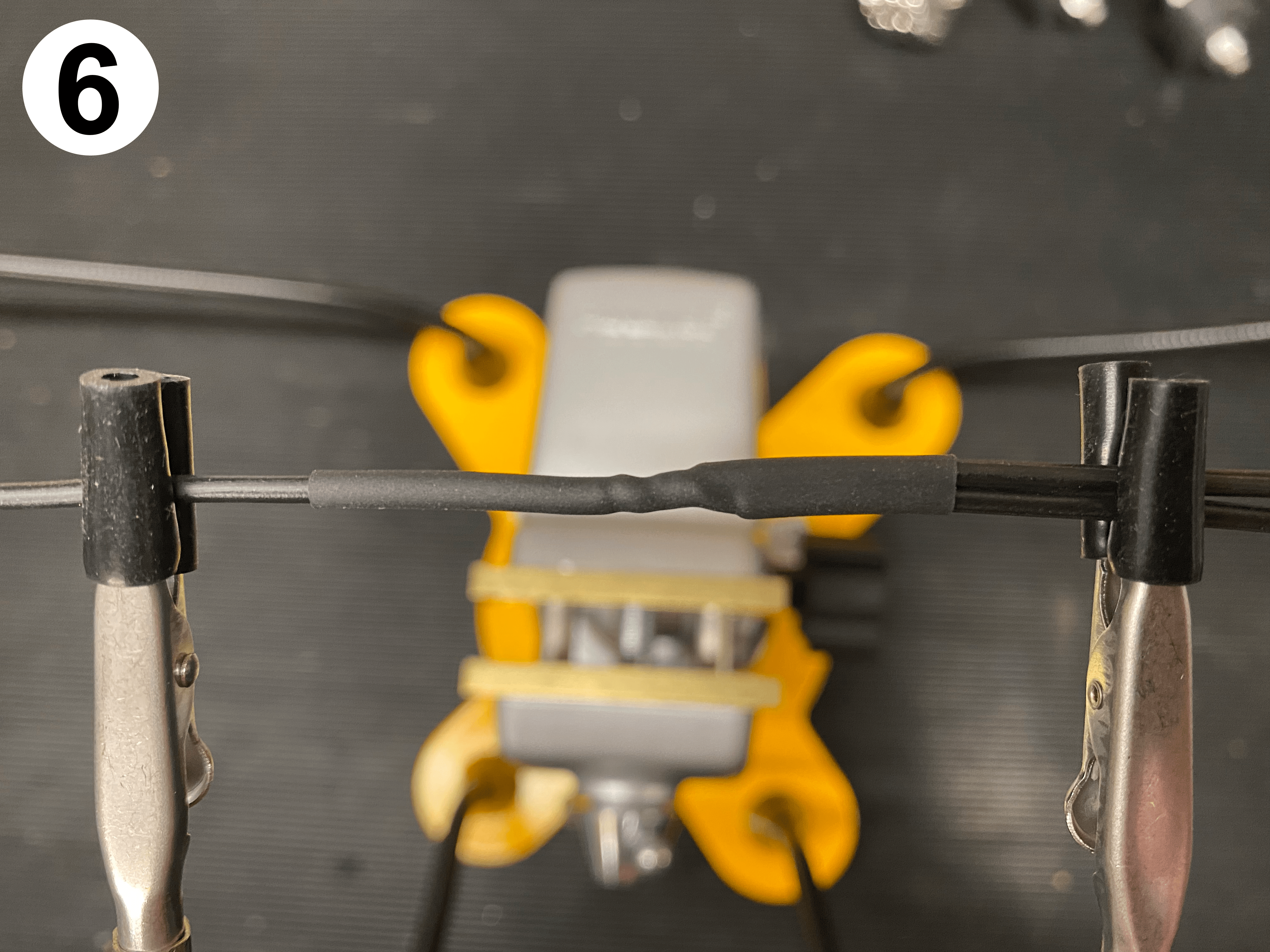
- Mark the cable where you want your tap to be
- Bare the wire using a craft knife, or automatic wire strippers
- Tightly twist your new branch wire onto the bared section
- Touch the soldering iron on to the joint, not too much solder, as you don’t want to make the whole section stiff and brittle
- Trim some heatshrink tubing (preferably adhesive lined) and thread it on
- Shrink the tubing in to place using a heat gun
I use a 24 volt soldering iron with a wide tip which I run at 450 degrees.
Hold the soldering iron under the twisted wire joint, then feed a little solder in to the top of the joint – nice and fast, and only the tiniest amount of solder needed.
For the connectors themselves, I do not like soldering – I much prefer to see a quality crimped connector – made utterly reliable using a decent and correct crimp tool.
When I have finished making the harness, and I wrap the whole thing in cloth tape, you’d never know there is a joint there!
The tape I like to use is Tessa 51608 fabric tape (it is also known as fleece tape)
It’s nice and furry, sticks well to itself and doesn’t come unraveled. It gives a great OEM look.
Cable Choice
Let’s look at the power consumers on the bike:
| Item | Description | Amps |
|---|---|---|
| 1 | Ignition (running) – approximate | 2.5 |
| 2 | Main Beam (60 watt or 45 watt) | 5.0 or 3.8 |
| 3 | Dip Beam (55 watt or 40 watt) | 4.6 or 3.3 |
| 4 | Pilot Bulb (5 watt) | 0.4 |
| 5 | Tail Light Bulb (5 watt) | 0.4 |
| 6 | Speedo Bulb (3 watt) | 0.3 |
| 7 | Tacho Bulb (3 watt) | 0.3 |
| 8 | Ignition Warning Light + Assimilator | 0.1 |
| 9 | Main Beam Warning Light (¼ watt) | – |
| 10 | Turn Signal Warning Light (¼ watt) | – |
| 11 | Turn Signal Bulb pair (21 watt each) | 3.5 |
| 12 | Stop Lamp Bulb (21 watt) | 1.8 |
| 13 | Horn | 3.5 |
When doing a rewire, select a cable that can comfortable handle to power draw.
“Back in the day” Lucas had their own spec for cables.
The typical cable sizes used by Lucas that we see on our classic bikes, are rated as follows:
- 44 strand
44/0.12 (44/0.30mm) 22 amp - 28 strand
28/0.12 (28/0.30mm) 14 amp - 14 strand
14/0.10 (14/0.25mm) 6 amp
14/0.12 (14/0.30mm) 7 amp - 9 strand
9/0.12 (9/0.30mm) 4 amp
Note 1 – the 14/0.10 was superseded in the 60s
Note 2 – modern cables of the same spec are rated higher than the figures Lucas give (as shown here)
The two companies that I use for my wiring are:
For the Norton guys, Club electrical guru Al Osborn of AO Services offers a wiring kit which you can see here.
The cable types I use on bikes are mainly:
Thin Wall Cable
- 32/0.20, 1.0mm², 16.5A – cable OD 2.0mm
- 28/0.30, 2.0mm², 25.0A – cable OD 2.7mm
Which are available in the colour ways that match our bikes harness
32 is the number of strands
0.20 is the diameter in mm of each strand
1.0mm² is the cross sectional area of the copper
16.5A is the nominal current rating of the cable
cable OD 2.0mm is the outside diameter of the cable (so the total diameter including the cable jacket)
Standard Colors
When you rewire a bike, it’s a great idea to use standard color coding.
This helps you and others easily troubleshoot issues, and trace back problems.
I have lost count of how many times over the years I have helped people with home grown wiring whose problems have been made worse by “helpful” people trying to lend a hand, and non-standard colour schemes causing issues.
This is even true of roadside recovery!
I have made a handy guide (including a downloadable page) that you can print out and stick on the wall of your shed or workshop.