


Marc Bischoff is based out of Fellbach in Germany.
Marc bought a bike from his birth year – a 1974 MK2a. He got it from a friend, and it has been stood for around 10 years.
What an exciting project!
His goal is to build a reliable bike, but maintain the patina.
The bike won’t be a museum piece – it will be used to travel through the Alps!
Wiring Choices
There are several choices available when considering a rewire.
There are a multitude of harnesses available ‘off the shelf’:
These are all made by the same company – Autosparks – the same company that built the wiring harnesses originally for our bikes!
However, each company has specified different criteria/materials/price points to Autosparks, so although they are made on the same fixture, they are not all identical in terms of quality.
Also remember that the piece of paper that comes in the box with the Lucas harness is STILL WRONG!!!
I have written about the errors in an article here.
(I have now given up trying to tell them this)
Marc is making a few changes to his bike and is looking for the best reliability, so he is going to make his own harness.
This is a fun process – bewildering for some, but if you take your time and go one step at a time, it’s actually quite a simple thing to do.
It helps that you have the original wiring for reference, and with the components already fitted to the bike, it is just a case of ‘stringing them all together’
Building your own means that you can take out all the unused bits (like the Interpol wiring) as well as the superseded bits (like ballast resistor, condensers, assimilator etc…
Positive Feed
One thing I like to do, and highly recommend that others do when making your own harness is use this as an opportunity to sort out earths (in our case the positive feed) once and for all.
With the Commando, Norton (and Lucas) were innovative in that there was no reliance on the frame as a ground for the majority of the components on the bike – for example, although the original zener diode sunk it’s heat to ground on the nice, chunky heat dissipating aluminium z-plate, and the component operated by electrically connecting via it’s mounting stud, there was still a ring terminal and a red wire on the back of it – I have gone into more detail about that in an article here.
The downside in the way Norton did it is that in many of the cases, each component has a positive loop – so there are two red wires going to it – look at it as an ‘in’ and an ‘out’ – if the wire breaks at the connector, or one of the connectors becomes unplugged, it can interrupt the positive feed to the rest of the bike.
If I am building a harness from scratch, I like to run a positive wire from the front to back of the bike, then tap in for a feed to each component as required – there is a massive advantage in doing this, and making it part of the loom, as it means you rule out any unreliability associated with bad earths, or trying to get power through rust, paint, powder coating, paper gaskets, loctite, clutch cables, steering bearings and speedo/tacho drives.
For the sake of spending an hour running this wire now, it means you rule out a massive variable, and make troubleshooting really easy in the future. So well worth doing in my opinion!
I have drawn a simple diagram that shows the negative wire with the splices for the individual components – I usually have a 12-gauge cable to handle this – a 2mm² cable will handle 25 amps which is more than enough.
When you splice into the cable to feed the positive to an individual component, you can use a lighter gauge cable that is rated for the maximum current that particular part will draw.
For example, the turn signals can have an 18-gauge cable – 1mm² will handle 8.75 amps and be more than enough.
Those old 21-watt lamps used in the turn signals will draw no more than 3.5 amps as a pair (front and rear).
Here is a diagram which covers the design for the positive ‘BUS’ that runs from front to back of Marc’s bike, with the splices to feed the individual components.

The above diagram can be downloaded as a PDF by clicking here:

Note that in the above diagram, I have drawn in a positive feed to the pilot light and both instrument backlights.
Sometimes these have a proper, wired positive connection, other times they earth out through the body of the lampholder.
I don’t understand the rhyme or reason to these lampholder types – I have seen two different types on two bikes of exactly the same year. But it is something to watch out for when you are running wires for your positive ‘BUS’
The other factor to note is the turn signal indicator ‘stalks’ – I have mentioned in other articles, that this is one to watch out for.
Originally the stalks were chromed plastic, and relied on this for the positive feed to the lamp.
It’s a really poor design, and I don’t like it – there is room inside the tube of the ‘stalk’ to run an extra red wire and do a proper job!
Wiring Technique
When I am making up looms and harness from scratch, I like to minimize the number of connectors I use – ideally using them only at the point the cables plug in to the components themselves.
This feels contrary to what they did back in the 60s on bikes, where you seem to run into connectors for the sake of it – these are potential points for moisture ingress, terminal corrosion (the dreaded verdigris) and ultimately failure.
If I am splicing like in the case of the positive ‘BUS’ (covered above) that I like to run from front to back of a bike, I like to bare the cable using wire strippers where I want my splice to be, I then twist the junction wire around the bared section, solder it, and use an adhesive lined heatshrink sleeve over the top which will protect the joint from moisture ingress and provide decent strain relief.
I feel that mechanically twisting the cables as I do, and then strain relieving them so well means there is zero risk of a soldered joint becoming dry or failing – I have certainly never had a failure in many years.
Here are some pics of my splicing procedure:


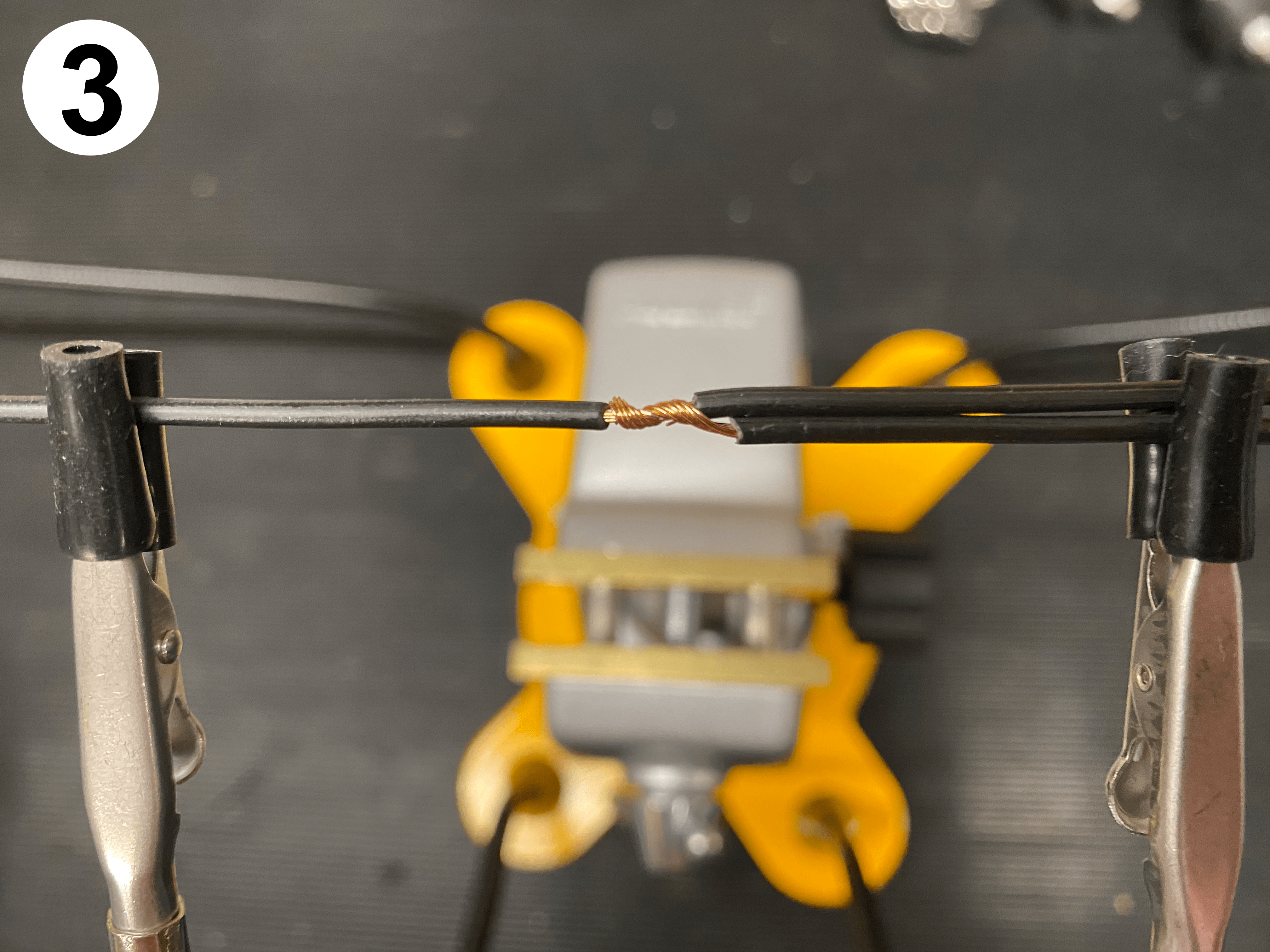
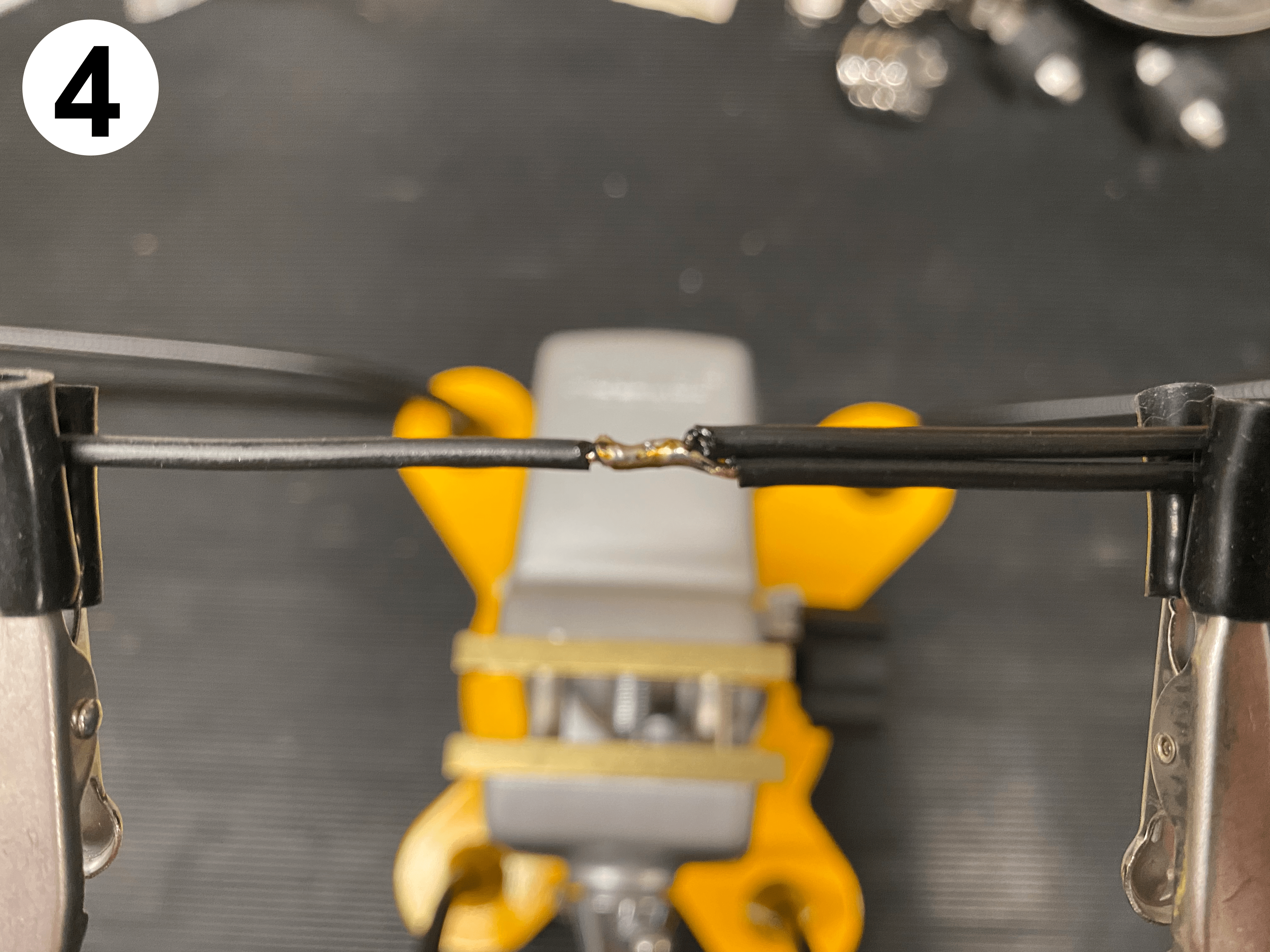
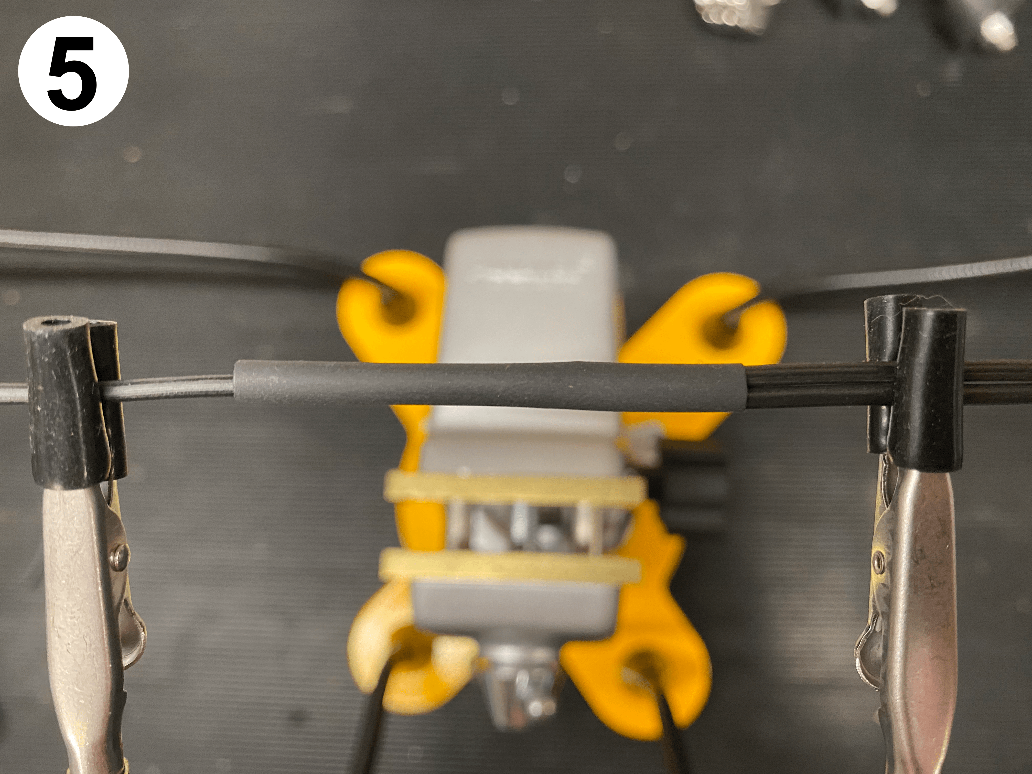
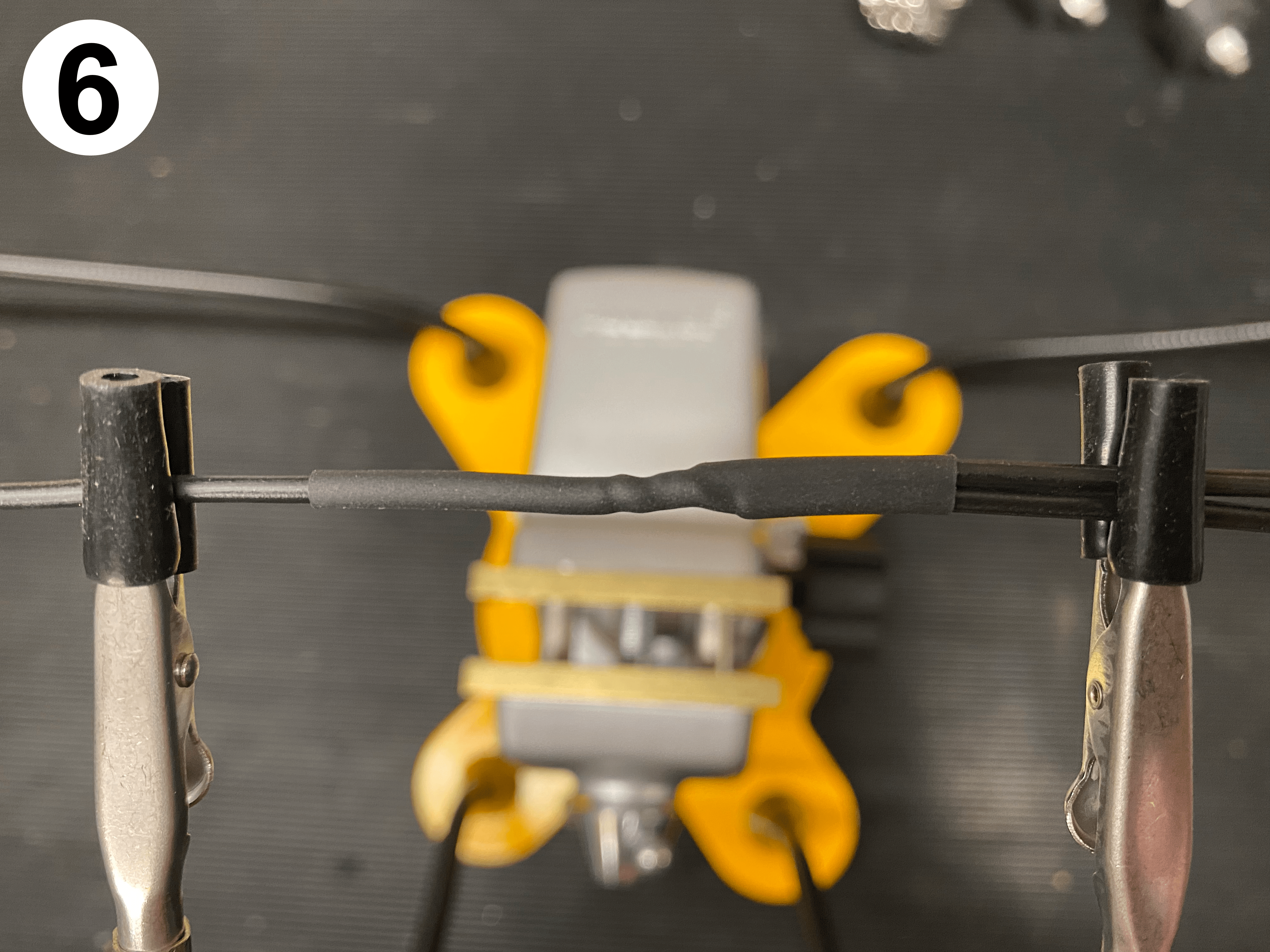
For the connectors themselves, I do not like soldering – I much prefer to see a quality crimped connector – made utterly reliable using a decent and correct crimp tool.
When I have finished making the harness, and I wrap the whole thing in cloth tape, you’d never know there is a joint there!
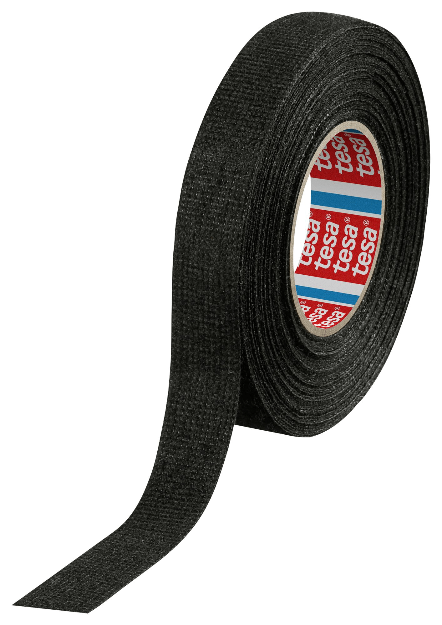
The tape I like to use is Tessa 51608 fabric tape (it is also known as fleece tape)
It’s nice and furry, sticks well to itself and doesn’t come unraveled. It gives a great OEM look.
Fuses
I have found issues with the glass-style fuseholders in the past – the springs become weak over time, and eventually the circuit becomes intermittent.
As the fuse disconnects and reconnects to the contacts, a small amount of arcing occurs – over time a layer of ‘soot’ will build up over the contact patch, which in itself acts as an electrical insulator.
This can impact all sorts of things, not least the smooth running of your engine!
The symptoms of this feel very much like fuel starvation, so most assume there is a carb problem before they even start looking at the electrics!
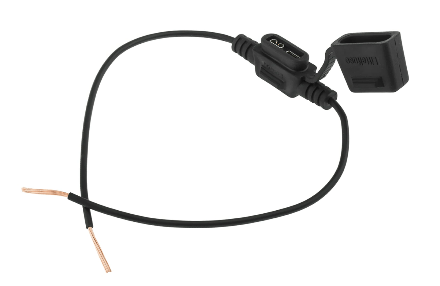
I would recommend using automotive blade type fuses all round instead of the original glass type used on these bikes.
These are great, as blade fuses are available in every garage and petrol station, and are very resilient to vibration.
My rule of thumb is usually a 15-amp fuse for standard bikes, or a 20-amp fuse for MK3s or if you have fitted high output alternator etc…
The other thing to watch with the old style fuses is the value.
Our workshop manual specifies a 35-amp fuse:

This was written in the 70s for a 70s british bike
It did not take into consideration that a US fuse is rated in a different way!
The British standard was to show the blow value on the fuse, and in the manual – not it’s continuous rating.
The US standard (which was subsequently adopted internationally) is to show the continuous rating value on the fuse, and in the manual.
Some fuses, back in the day showed BOTH their continuous rating value AND their blow value, but this was certainly not always the case.
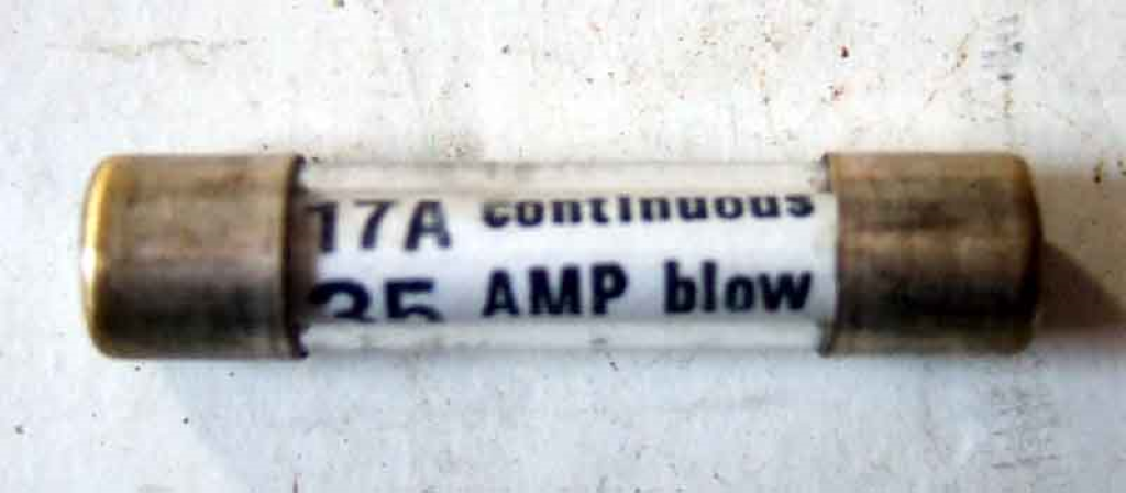
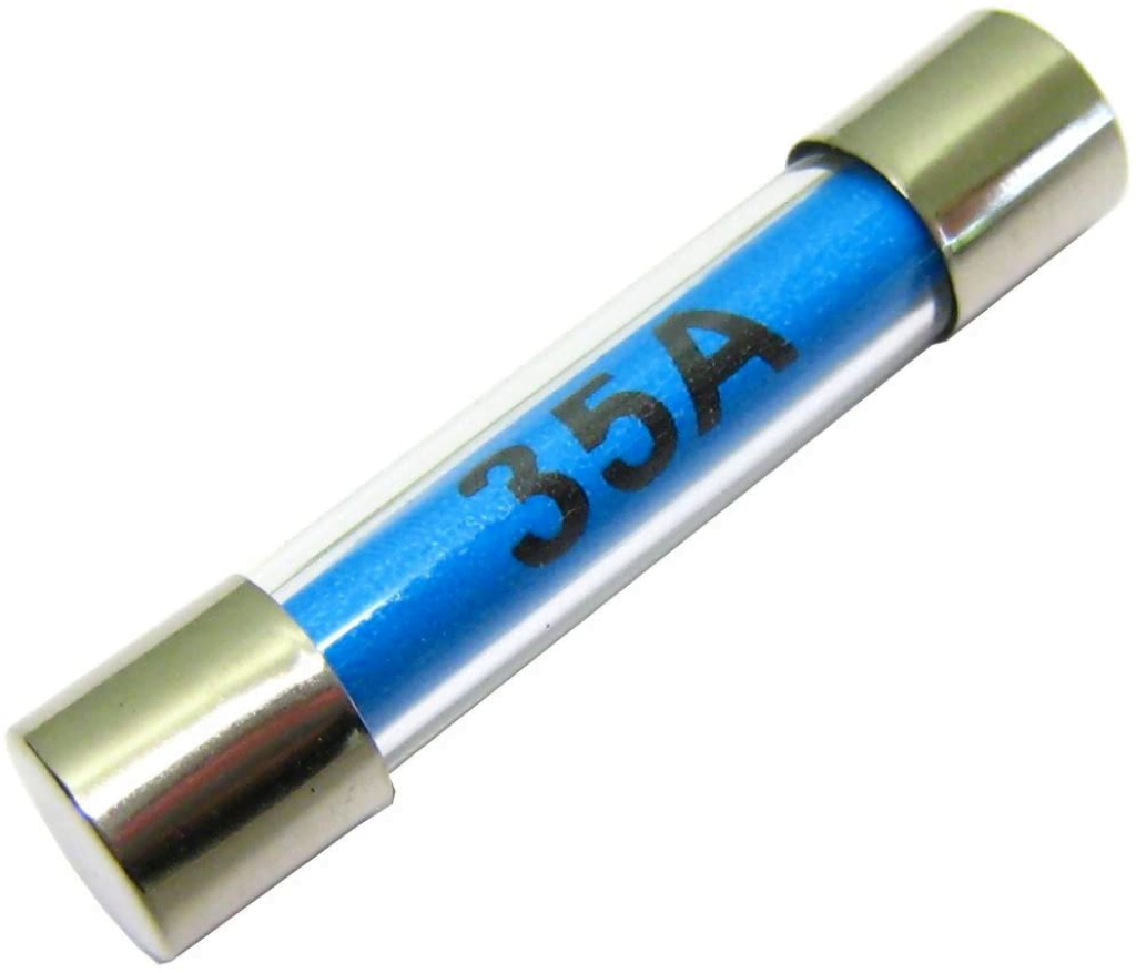
To this end, I see MANY bikes fitted with the wrong value fuse – a 35-amp continuous rated fuse will blow at 70 amps… a long time after every cable on the bike has melted.
Not good.
Modern blade type fuses are labelled and referred to by their continuous rating. Everywhere. Worldwide.
So, you know where you are, and there are no nasty surprises.
Electronic Ignition

A decent Norton Commando upgrade is to move from the old points-based ignition system over to Electronic Ignition. Marc’s MK2a was running an old Boyer Bransden.
Marc is fitting a unit that seems really popular these days – the Pazon Sure-Fire

These are popular for two reasons:
- COST – the are one of the lowest price units available on the market at the moment, and the come with an amazing seven and a half year warranty!!!
- RELIABILITY – people are nervous of the ‘shake and bake’ units like the Tri-Spark, where everything is all in one single, miniaturised unit behind the points cover. The Pazon is a carbon copy of the Boyer Bransden unit with a stator plate (Pazon call it the Ignition Trigger) and a separate box of electronics (which Pazon call the Ignition Module)


In fact, the similarities with the Boyer Bransden units don’t end there – all the wires are the same color too!
Actually, Andy and Debbie from Pazon both used to work for Boyer Bransden!!!
Moving from points to a Pazon Sure-Fire electronic ignition is a pretty simple upgrade.
From a wiring perspective, the most important thing to note is that you will be moving from a pair of coils that are wired in parallel to series.
Originally, the points make and break the positive (earth) side of each coil in turn.
The Pazon electronic ignition system uses a concept called “wasted spark” – with the two coils wired in series, they are energized together on every rotation of the camshaft.
You’ll note in the wiring diagrams below that the Ballast Resistor and Condensers have been removed as part of the conversion to Electronic Ignition.
The color coding of the wiring is simple:
| Wire Colour | Description |
|---|---|
| Red | This is the positive feed to the Pazon, and is spliced into the Positive bus. |
| Black | This is the negative supply FROM the Pazon TO the coils |
| White | This is the negative feed to the Pazon. It is joined to the White/Yellow that is the kill switch on your left side handlebar switch cluster |
| Black/Yellow Black/White | these go from the Pazon black box (they call it the Ignition Module) down to the Stator Plate (they call it the Ignition Trigger) that sits behind the points cover |
Alternator

Marc has very sensibly opted for a three phase alternator stator.
This is, in my opinion, a great option to go for and is far superior to the factory original single phase unit.
The spec is as follows:
- Lucas RM24
- 3 Phase
- 10.5 amp
- Part Number LU47252
- Also found under Part Number WW10193L
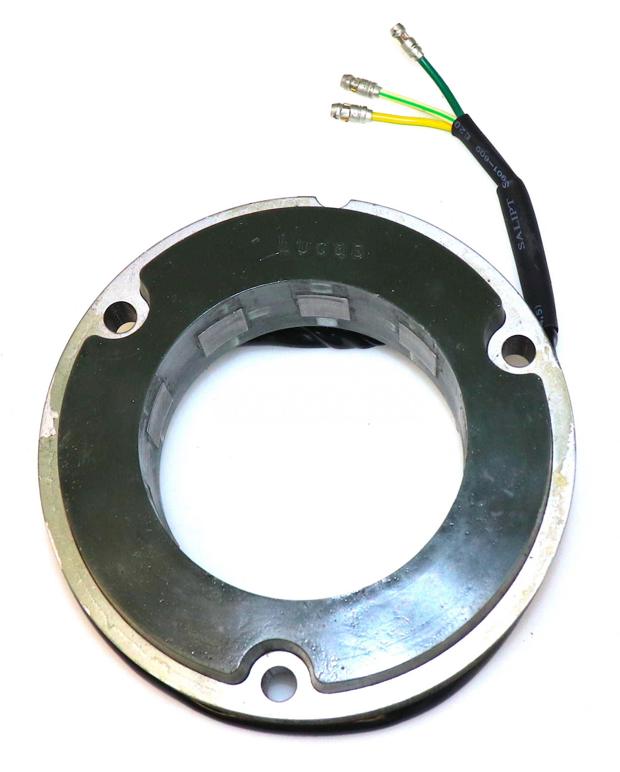
This stator is the standard output version, putting out around 10.5 amps – this is a sound choice on non-electric start bikes.
Although the output is about the same as the original RM21 single phase unit, with the three-phase unit, output is produced at a much lower RPM making this an ideal solution for around town and in stop start traffic conditions.
As always, I recommend that you ride with your headlight on, as this will always help with the longevity of the components that make up your charging system.
Regulator/Rectifier

Another of the most common upgrades or modifications for a classic british bike is to add a combined regulator/rectifier unit.
Our Commandos use a blue can capacitor, zener diode (which can be found mounted on the back of the z-plate) and rectifier unit.
A combined regulator/rectifier replaces all of these components with one package.
Marc has gone for the relatively new to market Tri-Spark MOSFET unit.
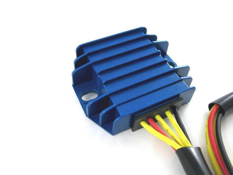
It is certainly easy to spot in it’s blue anodised heatsink!
There are five wires to connect:
| Wire Colour | Description |
|---|---|
| Yellow (x 3) | these are the AC input and pick up on the three wires coming out of the three phase alternator stator (connection can be any way round, as this is the AC side of the circuit) |
| Red | this is the Positive output and will be spliced into the Positive bus. |
| Black | this is the Negative output. This will sit between the Fuse and the Ignition Key Switch |
The spec on paper is very good, being able to handle up to 20 amps.
And the benefit of MOSFET is much more precise control of the charge voltage. I have done a deep dive into reg/rec types and behavior which you can find here
Here are the wiring instructions for the Tri-Spark VR-0030 MOSFET regulator/rectifier.
Warning Light Assimilator
The Lucas 3AW 3 wire ‘silver can’ assimilator is the most unreliable part of the bike in my opinion.
Think of the old-fashioned mechanical bi-metallic strip that is part of the thermostat on an old central- heating system – it’s basically the same sort of technology used here. Warming up and expansion/contraction of different metals to open and close contacts.
Couple that to a rattly, vibrating motorcycle, and you can suddenly understand why they were not wholly reliable.
Plus, there is the matter of what they are actually doing, and how much use that is.
The 3AW is looking for about 6 ½ volts coming out of the alternator stator.
It gives you no information about the charging (i.e., the regulator (zener) and rectifier)
It gives you no information about the state of the battery.
To this end, Marc has bought the BSM from Andover Norton

This looks like the same unit that Al Osborn sells.
13.1947 is available from Andover Norton’s website here.

It has two wires:
- positive, which will tie in on the positive feed ‘BUS’
- negative, which is picked up as the W (white) from pin 2 of the ignition switch
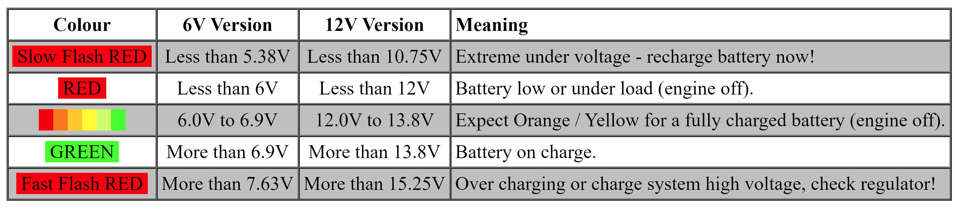
This provides you with a lot of far more useful information than the standard 3AW provides, plus it is solid state so is far more reliable.
The manual for the unit is here:
Tidy Up
Of course a few things went in lieu of the above upgrades.
The ballast resistor and condensers went when the new Electronic Ignition was added.
The zener diode, full wave silicon rectifier, and blue-can capacitor were discarded to make way for the new combined regulator/rectifier.
As part of building a new harness, we can also remove the power socket and superfluous Interpol wiring as well as the cluster of unreliable connectors under the tank.
This has made for a nice, simple and uncluttered wiring harness!
Wiring Diagram
Here is the Wiring Diagram for Marc’s MK2a.
Custom Norton Commando Wiring Diagram – Marc Bischoff PNG 3066×1841

This is also available for download as a PDF