
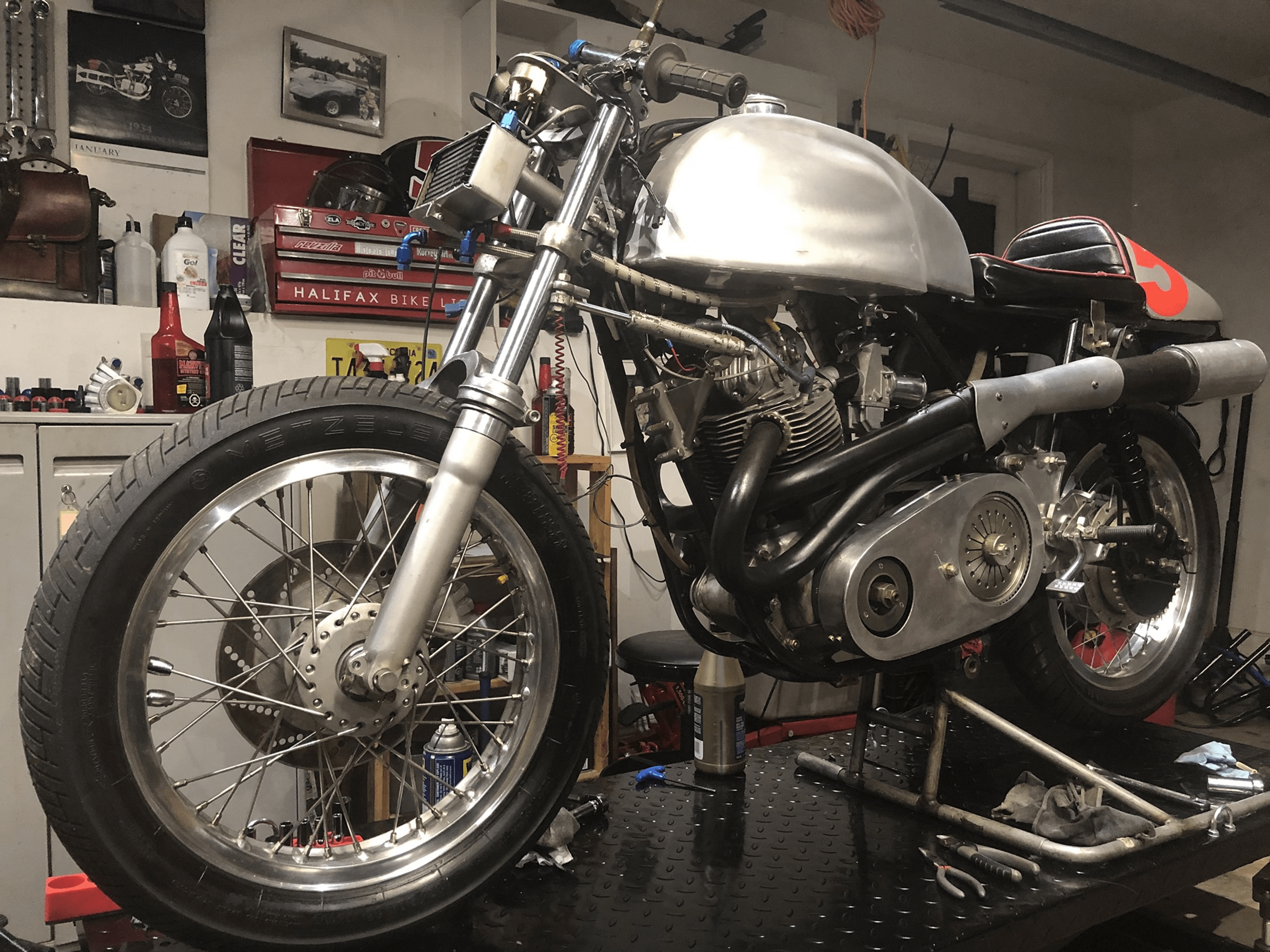
Michael Scott reached out to the Norton Commando Facebook group, as he had a query about a bike he has recently picked up.
He explains that the owner recently passed away, and this race bike has been sitting idle for the last twenty years.
Michael wants to get it up and running before he starts any kind of restoration, but didn’t understand the electrics on the bike.
There is a big 40mm belt drive from Steve Maney (along with several other nice go faster bits from Steve by the looks of it) but Michael could see no sign of an alternator or anything like that.

Total Loss
It’s not at all uncommon for a race bike to run total loss electrics (i.e., a freshly charged battery is connected up at the start of each race, and there is no provision for charging on the bike)
The mass of the rotor on the end of the crankshaft and the magnetic resistance as the rotor spins inside the stator has a cost of about 1% power output.
Not to mention the significant weight saving by removing all the superfluous road-related electrical equipment (lights, switchgear, brackets, horn, wiring harness, connectors etc…) all add up, so when seconds count on the track, it’s well worth doing!
Battery
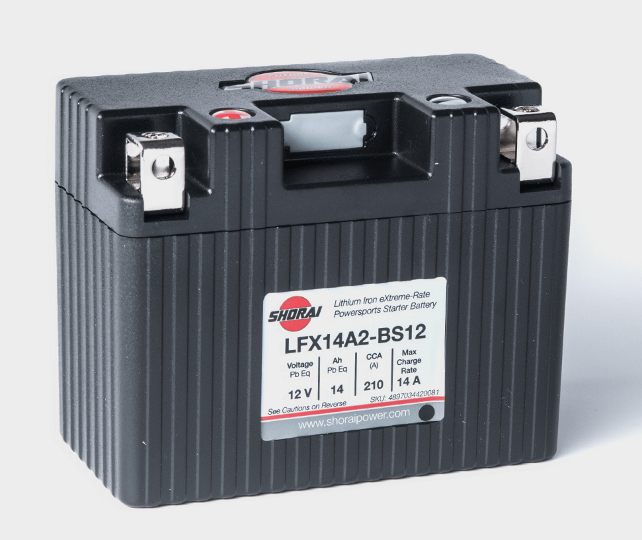
Another significant gain that can be made is with the weight of the battery – a modern lithium-based battery is typically featherlight versus the heavy road-going AGM/lead-acid equivalent.
Lithium-based batteries will give you a decent couple of hours run time, and can be safely charged off the bike using the correct, manufacturers balanced charger.
An ideal application for this battery type, and typically weighing in at 1.6lbs for a 14 amp-hour unit.
Ignition
Michael’s bike has a Boyer Bransden electron ignition fitted.
A really popular Norton Commando upgrade is to move from the old points-based ignition system over to Electronic Ignition.
One of the most common units of the time is Boyer Bransden, who have been around since 1969.
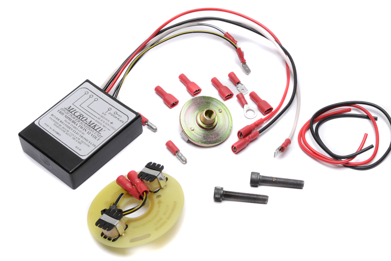
They are still going today, and their website can be found here.
Moving from points to Boyer electronic ignition is a pretty simple upgrade.
From a wiring perspective, the most important thing to note is that you will be moving from a pair of coils that are wired in parallel to series.
Originally, the points make and break the positive (earth) side of each coil in turn.
The Boyer electronic ignition system uses a concept called “wasted spark” – with the two coils wired in series, they are energized together on every rotation of the camshaft.
The color coding of the wiring is simple:
- The Red – this is the positive feed to the Boyer, and is usually picked up from the red wire that goes to the Coil positive terminal.
- The Black – this is the negative supply FROM the Boyer TO the coils.
- The White – this is the negative feed to the Boyer in a total loss system this will go directly to the battery negative terminal via a switch and a fuse.
- Black/Yellow and Black/White – these go from the Boyer black box (they call it the Transistor Box) down to the Stator Plate that sits behind the points cover.
Ignition Switch
What you use here will vary depending upon what class you race in, and what their rules are.
In it’s simplest form, the ignition switch could be a large, robust, industrial spec toggle switch like this one:
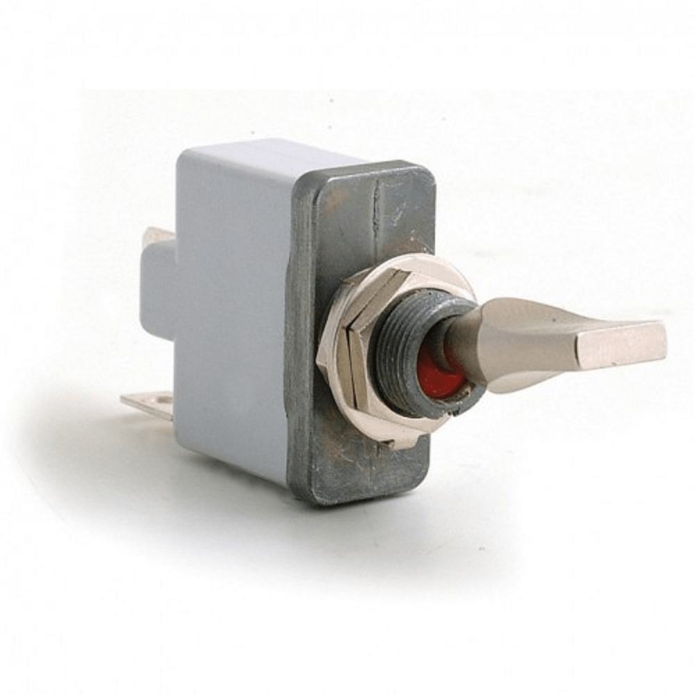
Like all examples here, the goal is to make or break the negative connection to the battery.
The next example is the kill switch.
This is a normally closed button which opens (breaks) momentarily when you press it, which cuts the power to the ignition and stops your engine.
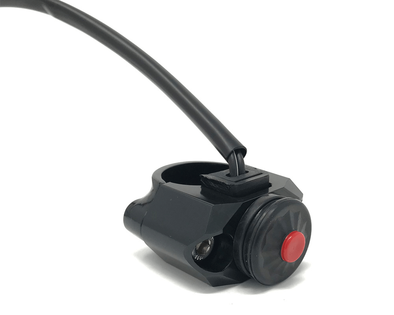
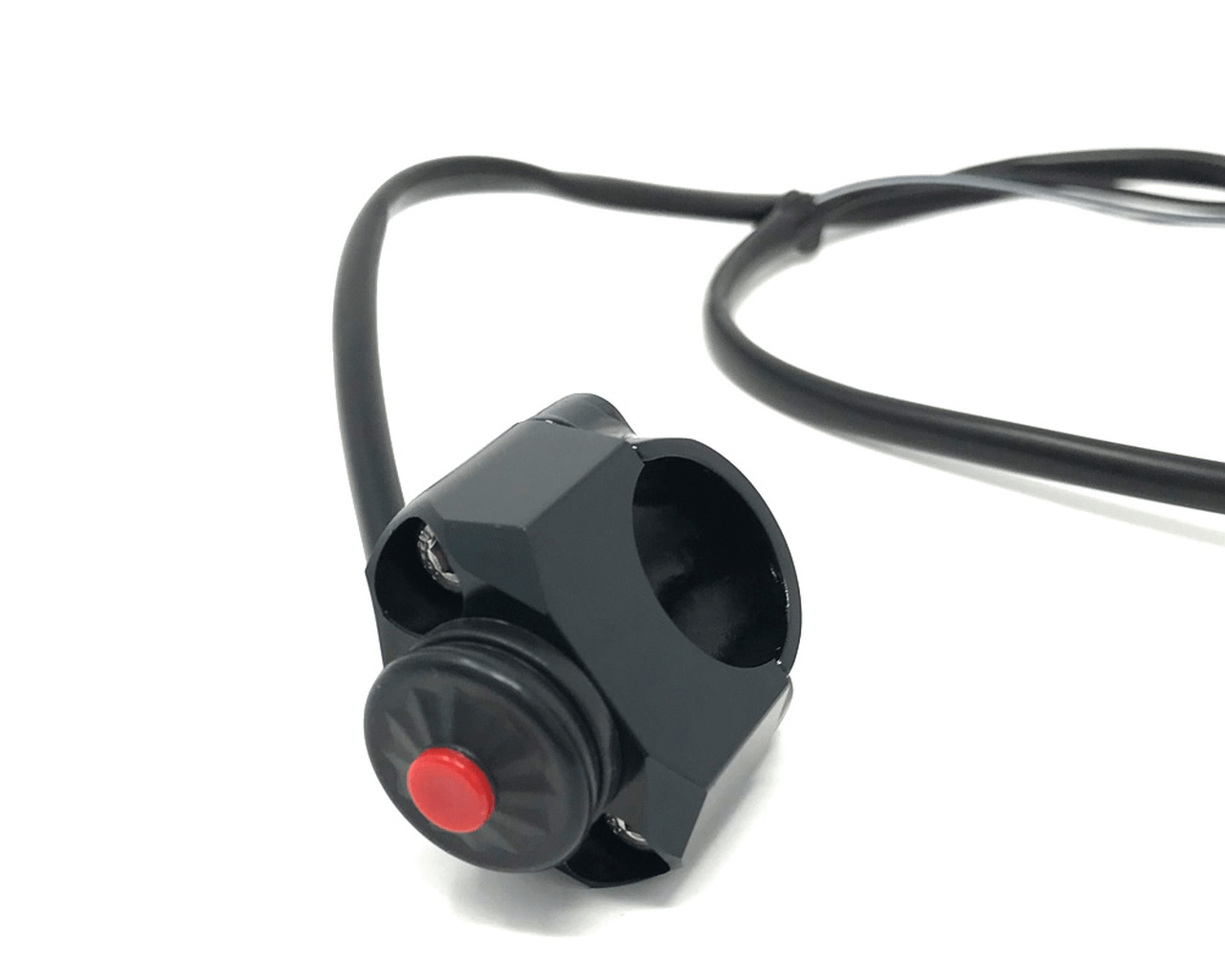


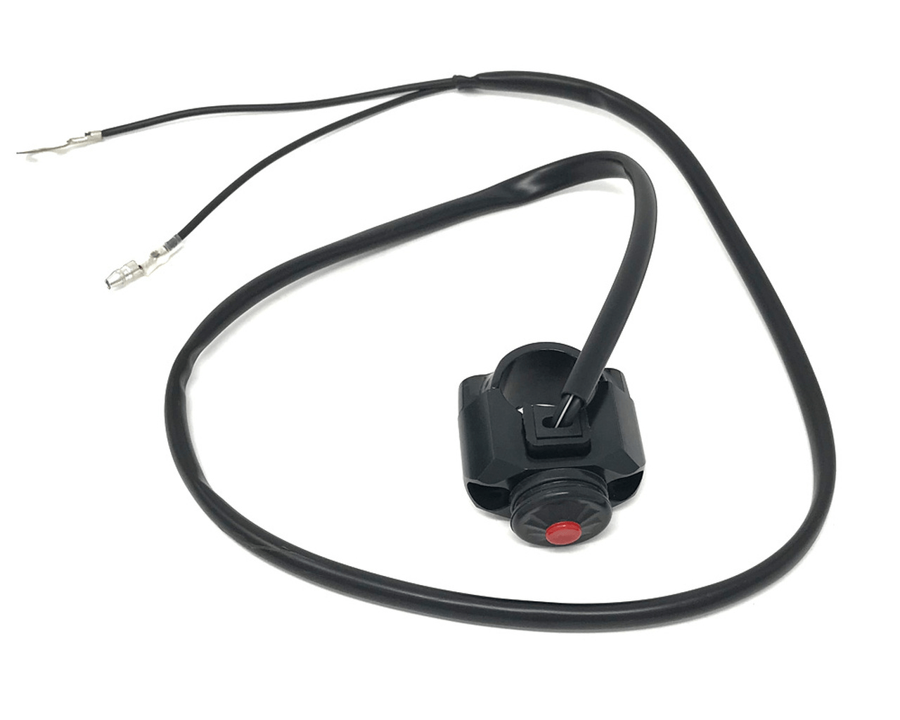
The downside of this switch type is that you would need to install a separate switch to turn the ignition off, when you are not running, or be sure to disconnect the battery, otherwise it will flatten.
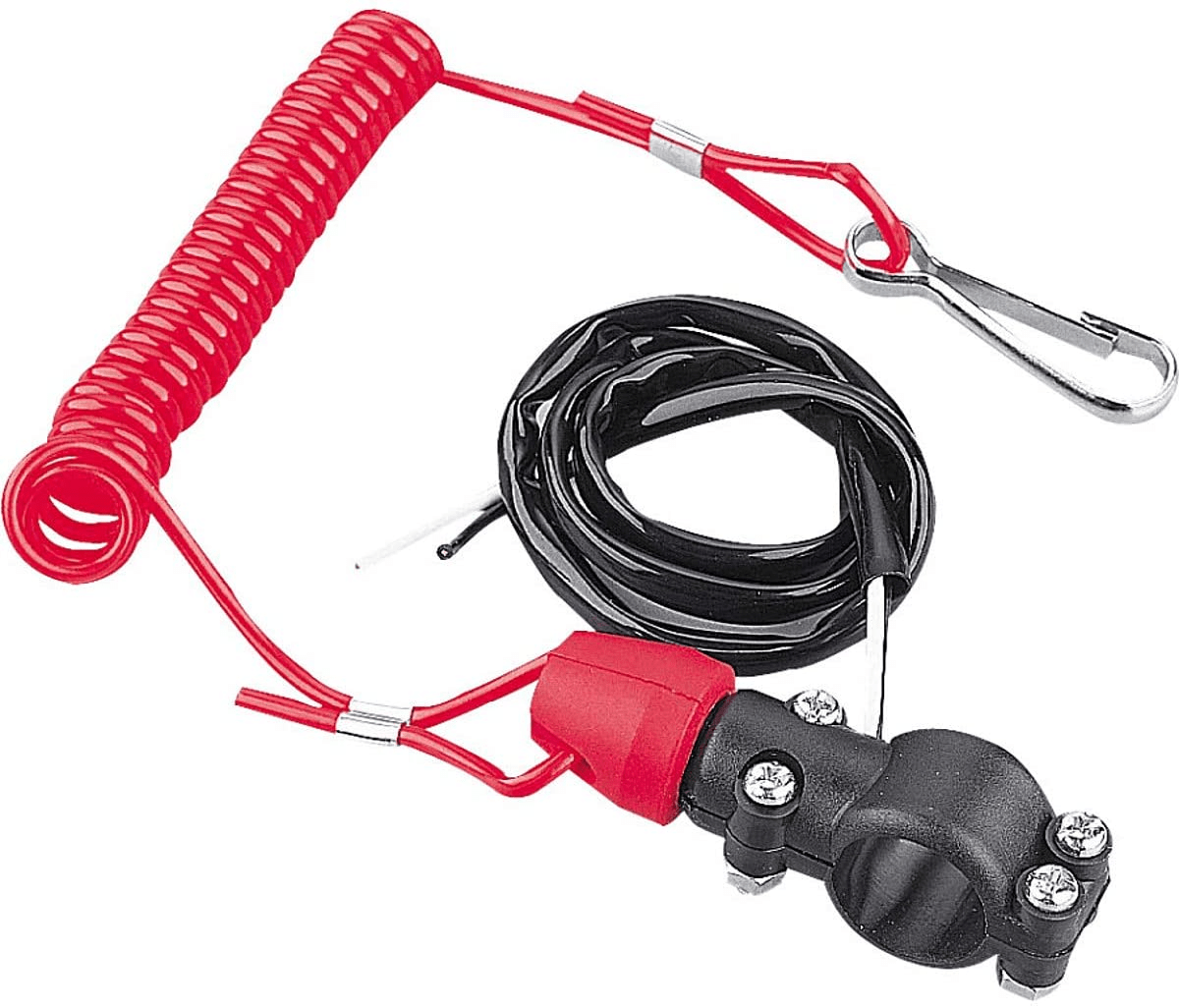
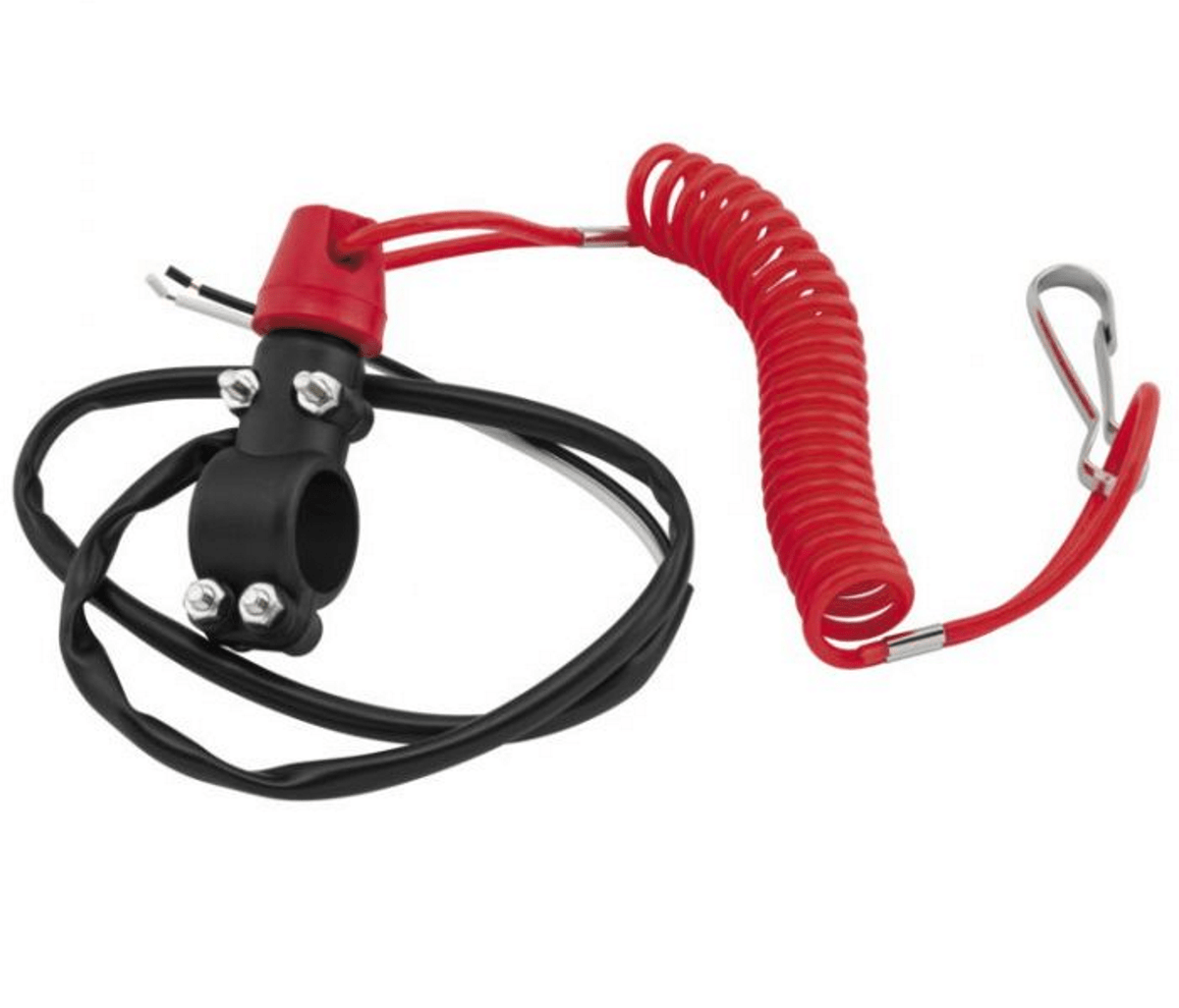
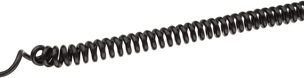
The next option is morbidly known as the Dead Man’s Cord – very common on watercraft like small boats with outboard motors and jet-skis.
The idea is to wear a line around your wrist and if you fall off, or are separated from your vehicle, the power to the ignition is cut.
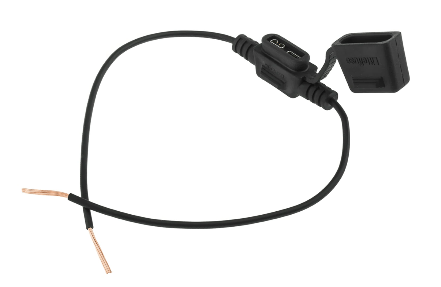
I have seen home made versions of these tether-type switches made from a ¼” (6.35mm) inline audio jack and socket. You see these on audio headphones.
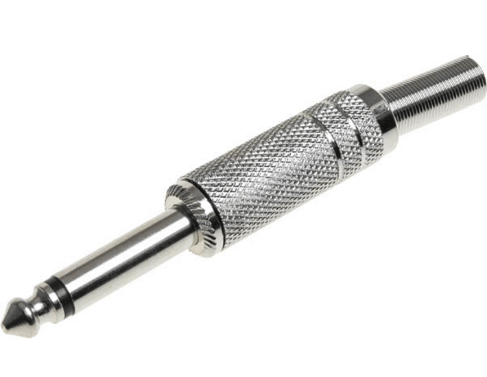
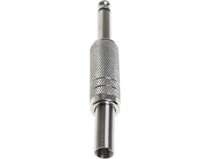
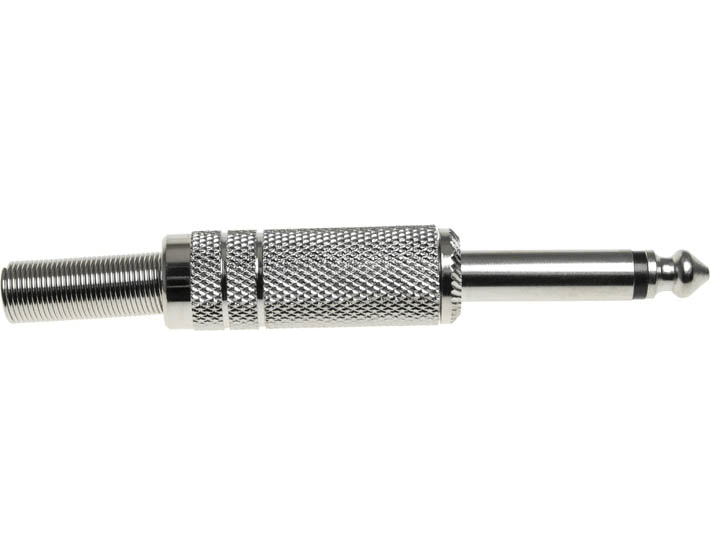


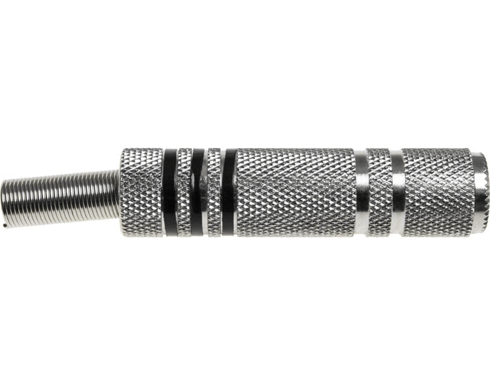
The nice idea of doing this is ease of availability (most high street electronics stores sell these) and very low cost.
You can have a collection of sockets in the toolbox ready to go, should one get lost.
The plugs and sockets are very simple in their construction, there is nothing to go wrong, and the large contact area means they can easily cope with the current you pull through them.
The final option is the combined kill switch and tether. Again, these are readily available, as you see them used on ATVs and quad bikes.
They have both a push to break kill switch, and a dead man’s cord on the same handlebar mounting.
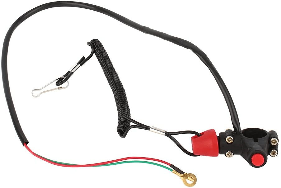
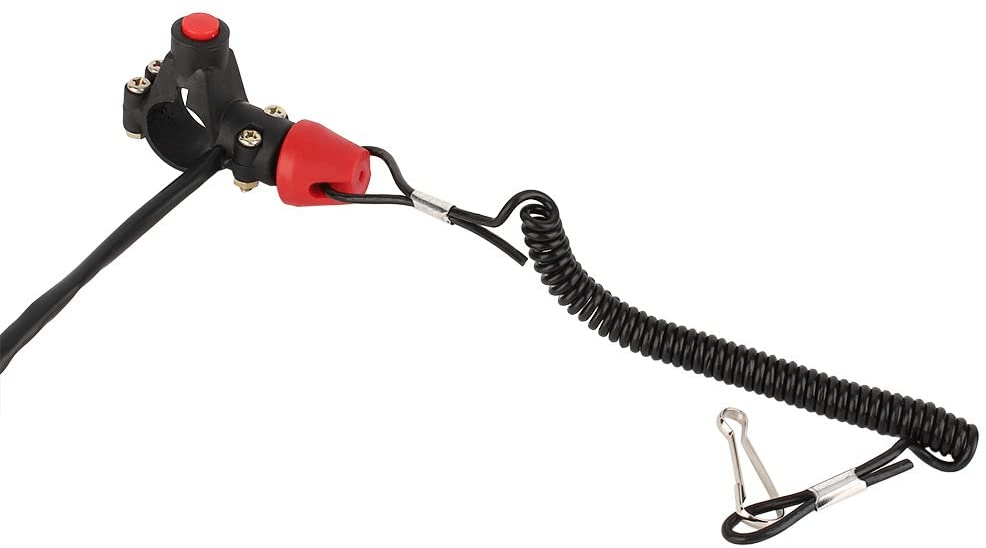
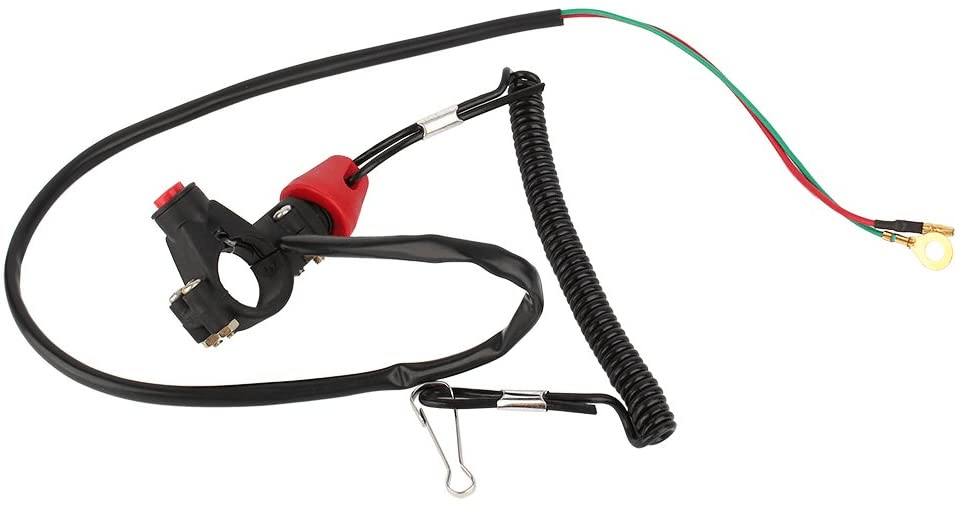
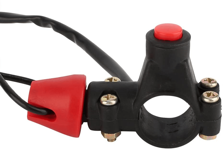
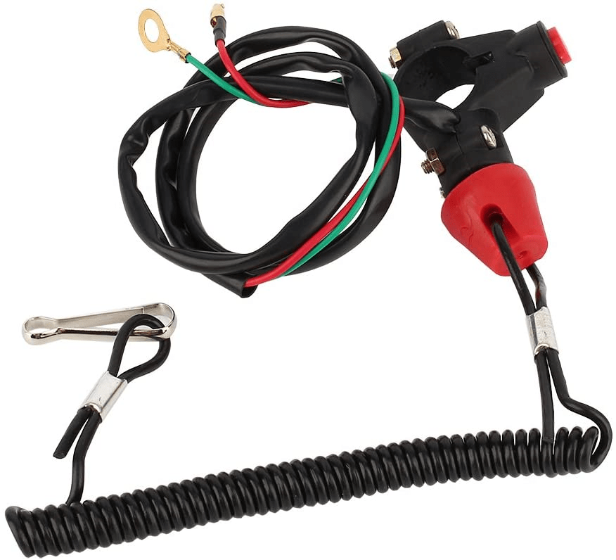
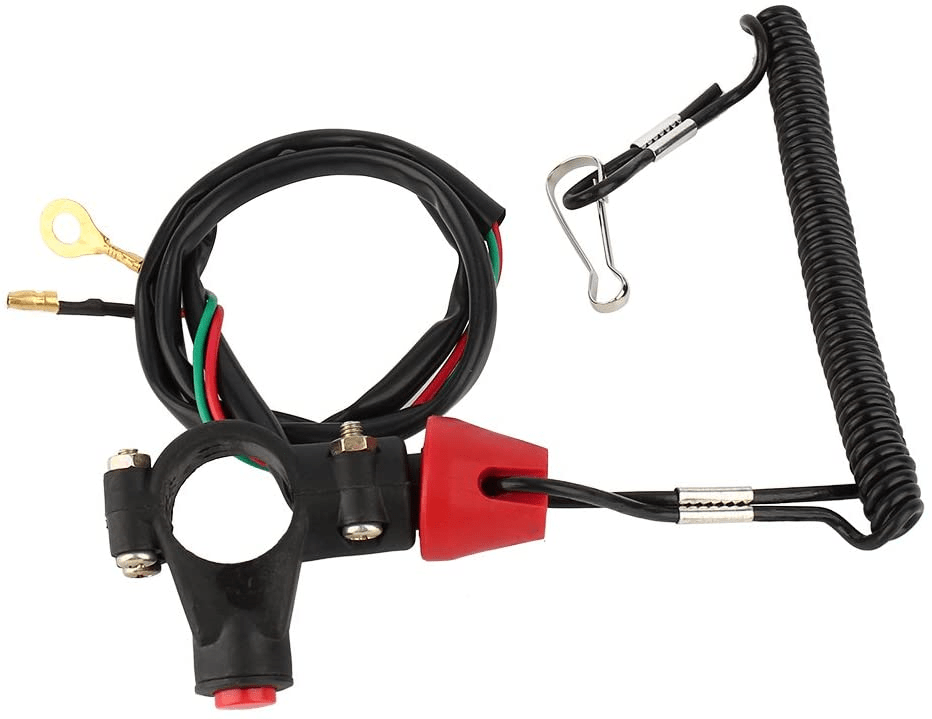
So you can pull out the tether when you are not running the bike, saving from disconnecting the battery manually.
The only thing I don’t like about these is the quality – all the ones I have seen are constructed from chinesium, and they feel like they are not going to last well.
It would be a shame for a bike to conk-out (technical term) on a race track in the ride of your life dues to a poor electrical connection in your kill switch!
Whichever route you choose to go up, any of the can be inserted between the (1) and (2) Master Switch pins in the below wiring diagram.
Fuse
I always feel it is important to add a fuse, and a race bike is no exception.
I have found issues with the glass-style fuseholders in the past – the springs become weak over time, and eventually the circuit becomes intermittent.
As the fuse disconnects and reconnects to the contacts, a small amount of arcing occurs – over time a layer of ‘soot’ will build up over the contact patch, which in itself acts as an electrical insulator.
This can impact all sorts of things, not least the smooth running of your engine!
The symptoms of this feel very much like fuel starvation, so most assume there is a carb problem before they even start looking at the electrics!
I would recommend using automotive blade type fuses all round instead of the original glass type used on these bikes.
These are great, as blade fuses are available in every garage and petrol station, and are very resilient to vibration.
A 5 amp fuse would be ok.
However, I’d run with 7.5 or 10 amp.
You wouldn’t want your engine to stop on the track just because the fuse rating was marginal on the power draw.
Earth
The final thing to note is the option I have taken for earthing.
As I have mentioned in numerous posts before, on the Norton Commando the engineers at Lucas and Norton were worried about the Isolastic drivetrain mounting causing earthing problems, so in the main part ran earth wires (which should really be referred to as positive feed wires) between electrical components on the bike, rather that earthing out through the frame.
With one or two minor exceptions, this resulted in a reliable and robust electrical system.
I really like the concept of not relying on the frame for the ‘earth’ so whenever I can, I will always recommend running separate wires instead of earthing out to the frame.
It gives you a much more reliable electrical system!
As you can see in the wiring diagram below, I have taken on the positives to ring terminals which all meet at the cylinder head.
This will give you the best possible spark, and least possible to go wrong.
Wiring Diagram
Norton Commando Wiring Diagram – total loss, ignition only – PNG 2048×1244
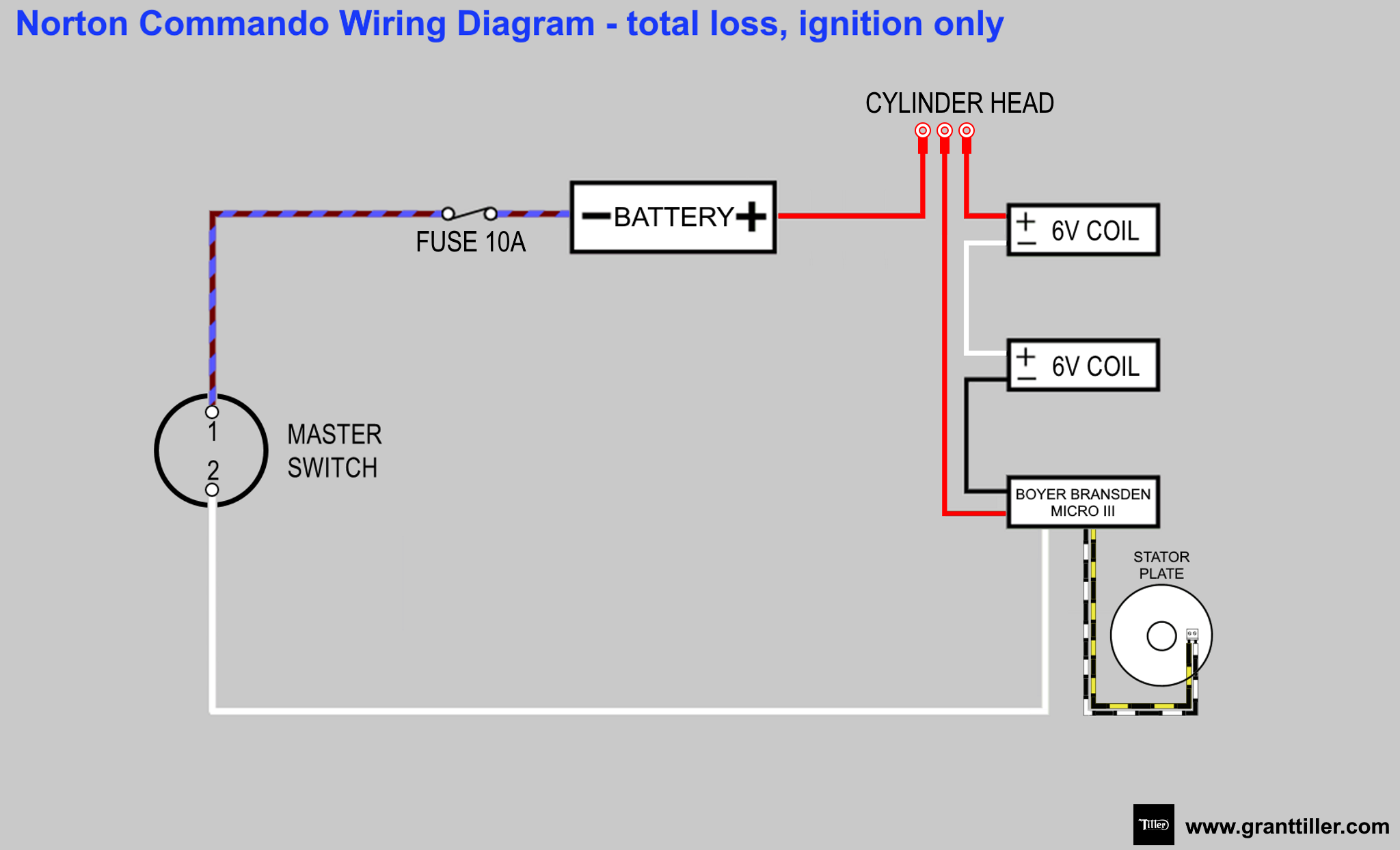
This is also available for download as a PDF
Update
Michael has just posted to Facebook a link to a video where he starts this absolute weapon for the first time! WOW!
Categories: Custom Wiring Diagrams, motorcycles