This is a custom wiring diagram for Mike Warner who has a 1971 Norton Commando.
He has a couple of Boyer Bransden upgrades on his bike which will be covered in this article.
Electronic Ignition
A really popular Norton Commando upgrade is to move from the old points-based ignition system over to Electronic Ignition.
One of the most common units of the time is Boyer Bransden, who have been around since 1969.

They are still going today, and their website can be found here.
Moving from points to Boyer electronic ignition is a pretty simple upgrade.
From a wiring perspective, the most important thing to note is that you will be moving from a pair of coils that are wired in parallel to series.
Originally, the points make and break the positive (earth) side of each coil in turn.
The Boyer electronic ignition system uses a concept called “wasted spark” – with the two coils wired in series, they are energized together on every rotation of the camshaft.
You’ll note in the wiring diagrams below that the Ballast Resistor and Condensers have been removed as part of the conversion to Electronic Ignition.
The color coding of the wiring is simple:
- The Red – this is the positive feed to the Boyer, and is usually picked up from the red wire that goes to the Coil positive terminal.
- The Black – this is the negative supply FROM the Boyer TO the coils.
- The White – this is the negative feed to the Boyer. This joins in to the White/Blue wire that used to feed the Ballast Resistor that you are removing. As standard, this goes up to the big connector block under the tank, where it’s joined to the White/Yellow that is the kill switch on your left side handlebar switch cluster.
- Black/Yellow and Black/White – these go from the Boyer black box (they call it the Transistor Box) down to the Stator Plate that sits behind the points cover.
Regulator/Rectifier
Another very common ‘upgrade’ or modification for a classic british bike is to add a combined regulator/rectifier unit.
Our Commandos use a blue can capacitor, zener diode (which can be found mounted on the back of the z-plate) and rectifier unit.
A combined regulator/rectifier replaces all of these components with one package.
One popular manufacturer of these is Boyer Bransden.

Boyer state in their documentation that their Power Box reg/rec is not compatible with the Warning Light Assimilator found on the Norton Commando, so the assimilator must not be used.
However, for those still wanting some kind of indication as to whether or not their charging circuit is working, the do offer a Power Box reg/rec that has a built in charging light.
This means that we need to remove the factory assimilator, and re-purpose the cabling up to the warning light in the headlamp shell.
A copy of the fitting instructions can be found here:

There are six wires to connect:
- Two Yellows – these are the AC input and pick up on the Green/Yellow and Green/White (connection can be any way round, as this is the AC side of the circuit)
- The Red – this is the Positive output and will join to the red wire if you are using existing wiring (it goes straight to the ground/earth of the frame)
- The Black – this is the Negative output (known as the hot wire) – it will pick up on the Brown/Blue wire (which goes via a fuse straight to the battery negative terminal)
- Red/White – this connects to the red earth wire and the standard positive earth wiring.
- White – this would typically connector to the old W/N (white/brown) that used to go to the old warning light assimilator. Eventually it will lead to the Warning Light in the headlight bucket.
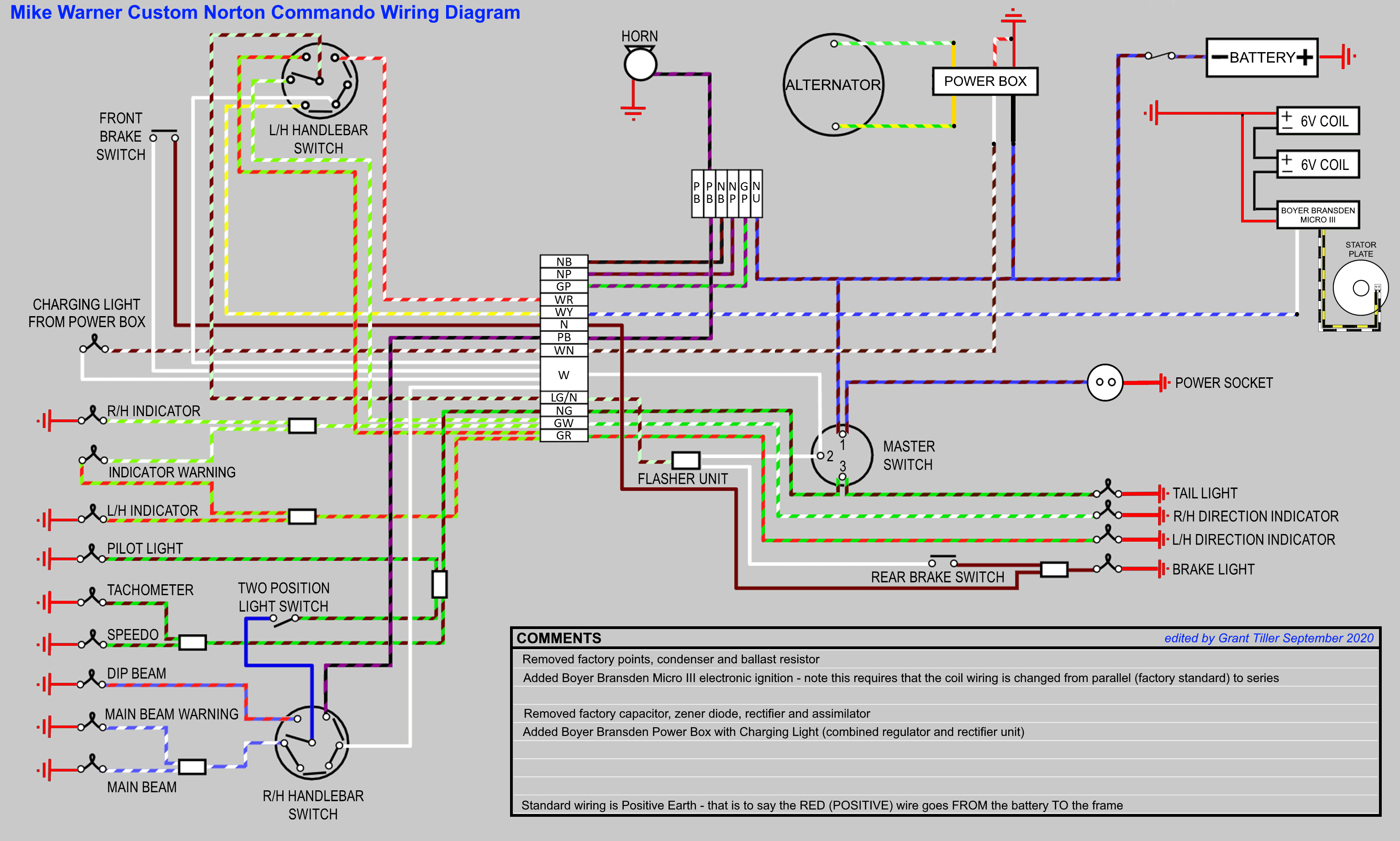
Wiring Diagram
Here is a custom wiring diagram for Mike Warner’s 1971 Norton Commando
Custom Norton Commando Wiring Diagram – Mike Warner PNG 3066×1841